-
Notifications
You must be signed in to change notification settings - Fork 2
thestumbler/alpha
This commit does not belong to any branch on this repository, and may belong to a fork outside of the repository.
Folders and files
| Name | Name | Last commit message | Last commit date | |
|---|---|---|---|---|
Repository files navigation
Module: alpha.scad
Author: Chris Lott
Description: Implement text in OpenSCAD using the simple technical
lettering styles used in drafting. This is a vector-style
of "font".
I'm using the following two modules:
1. arc.scad
by Alex Franke (codecreations), March 2012
http://www.theFrankes.com
Licenced under Creative Commons Attribution - Non-Commercial - Share Alike 3.0
Modified by rclott 2015-01 to extrude square or circular cross sections
2. ascii.scad
ASCII lookup table and other utility functions
from user MichaelAtOz
date 16 Jun 2013
on OpenSCAD github, issue #116 discussion thread:
openscad/openscad#116
Detailed Notes:
===============
Technical Lettering used in Drafting
see Wikipedia:
http://en.wikipedia.org/wiki/Engineering_drawing#Technical_lettering
Historical (pre-computers) technical lettering styles can be found
in various references:
http://p3cdn4static.sharpschool.com/UserFiles/Servers/Server_926913/Image/Migration/vertical_lettering.jpg
http://1.bp.blogspot.com/_nm98fXNhUco/TDHJMNGx9lI/AAAAAAAAAGM/JcZuvE6f_g8/s1600/Picture8.jpg
http://3.bp.blogspot.com/_nm98fXNhUco/TDHIM8VktBI/AAAAAAAAAF8/CSbxvOlo8pk/s1600/Picture5.jpg
In modern era,
European standards specify ISO-3098
American standards specify ANSI-Y14.5M-2009
An interesting discussion on this FreeCAD discussion forum:
http://forum.freecadweb.org/viewtopic.php?f=8&t=4349
from which we find the following ttf fonts, specifically designed
to follow these technical lettering drafting standards
1. Micronus / Y14.5M-2009
http://www.fontspace.com/micronus/y145m-2009
2. osifont / ISO-3098
http://code.google.com/p/osifont/
This OpenSCAD module uses the pre-computer styles, which in turn
seem to have been the model for the ANSI standard. Furthermore, an
approximation is made for some letters to avoid the missing ellipse
extrusion capability in OpenSCAD.
Wikipedia notes that ISO standards implemented certain features to
improve legibility (except for the "one" glyph, I don't see these
features in the osifont ISO-look-alike font):
(a) serifed "one"
(b) barred "seven"
(c) open "four", "six" and "nine"
(d) rounded top "three"
I have implemented these, except "d" which I don't understand.
And furthemore, I chose to add the following for legibility reasons:
(e) a diagonal bar through my zero glyph
(f) a bar on the "Z"
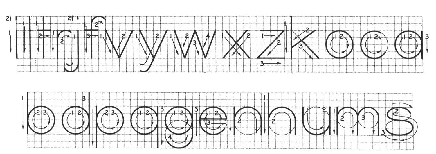
Each letter is descibed by a combination of line and circular
segments (some letters actually require elliptical segments,
for which I substituted ovals instead).
Each line segment is described by two points, beginning and ending,
in a vector as follows:
[x0,y0, x1,y1]
Each cicular segment is described by a center point, radius,
and beginning and ending angle in a vector as follows:
[x0,y0, rad, abeg,aend]
Each letter is described in a vector whose elements are as follows:
[
ascii_code,
name,
width,
vector_of_line_segments,
vector_of_circular_segments
]
The diagrams available to me seemed to use the following grid.
Not sure if this is spelled out in the two standards or not, but
it's easy enough to scale these letters to any desired size.
Uppercase letters are all constructed in a grid which is 6 units tall,
and most characters are either 5 or 6 units wide. Lowercase letters
are typically 4 units tall, with a few letters being 6 units tall.
Those letters with descenders extend two units below the baseline.
(per the referenced lettering charts shown above).
Stroke thickness should be 10% of character height.
I've assigned the arbitrary coordinate system to the grid:
0 1 2 3 4 5 6 7 8 9
6 + + + + + + + + + +
5 + + + + + + + + + +
4 + + + + + + + + + +
3 + + + + + + + + + +
2 + + + + + + + + + +
1 + + + + + + + + + +
0 + + + + + + + + + +
-1 + + + + + + + + + +
-2 + + + + + + + + + +
0 1 2 3 4 5 6 7 8 9
Letters are drawn by extruded squares or circles. It would be
straightforward to draw the with any arbitrary extruded polygon
with only minor changes to the code.
One note on the "end caps" of the lines. For circular letters,
it's easy to make all end caps a sphere. But for rectangular
cross section letters, a similar cap of a truncated pyramid
doesn't look as good when line segments join. To properly join
such line segments as a bigger headache than I wanted to endure.
I compromised by making circular segments have truncated
pyramidal endcaps, but line segments have half a cube (the line
segment is essentially extended by half the cross section length).
This is an adequate compromise, and frankly I liked the circular
cross section letters best, so I didn't pursue this further.
About
Simple technical lettering for OpenSCAD
Resources
Stars
Watchers
Forks
Releases
No releases published
Packages 0
No packages published