This document was originally written somewhere around 2002 and is based on the accumulative knowledge I required over the years from about 1996 up to 2001 having to work on a number of Windows applications that required a relativity low-level handling of Win32 bitmaps. I do not know if any of this information is still relevant. I haven't done any Windows programming for about 15 years or so.
I have taken the liberty to do some editing such as fixing spelling mistakes and reworking of super weird sentences, but on a whole, the document is pretty much in it's original form. If I would write this document today then I probably write certain things differently.
I haven't compiled or tested the examples for this publication. I noticed that the code was written in a C like C++ dialect. I guess that at the time the C++ compiler was more forgiving than a C compiler was (i.e. less strict). In those days though, I was using both Microsoft Visual C/C++ and Watcom C/C++ compilers, so the code should work with either of those (from that era).
Luke, January 2018
Over the last decade the Windows environment has become the most popular operating system known to the world. It’s the most used operating system and to this day, probably holds the biggest developers community. With the birth of the 32-bit version, the Windows environment has grown and proved to be a system not only to be used in a business environment but also to be a great system for the entertainment market. With the introduction of DirectX, Microsoft has set foot in the door to this market and Windows has become the number one operating system for games, multimedia and other graphical applications.
But, as Windows was introduced to the world, developers were also introduced to a totally new way of developing their software. Not only the structure of your program completely changed, you now also had to consider the Windows graphical user interface with all its shortcomings and pitfalls.
The graphical user interface used in Windows known to developers as GDI (Graphical Device Interface) has, over the years, become the subject of many discussions and maybe even more mistakes. The GDI is known as a so called ‘state machine’ which for GDI basically means that, if you have used it you must leave it in the state you found it when you're done using it. Well, this may seem like a reasonable task but has caused many developer many late night hours of debugging and headaches.
This document will only cover one aspect of GDI and is probably one of the most misunderstood aspects of GDI in general. Therefore this document will focus on bitmaps and their palettes. I’ll assume you have some basic knowledge of Windows programming and that you know what a Device Context is. If you don’t, you’re probably not ready to read this document and you should get yourself some material on GDI and Windows programming in general first.
Bitmaps are probably one of the most used GDI elements used in Windows. Without even noticing it, most of the elements you see on your screen are bitmaps. From the client-area of your window to the scrollbars and buttons you control your actions with. Although most of these elements are ‘drawn’ by GDI, they end up to be a bitmap. Most of the time you don’t have to worry about these things, GDI will handle most of the dirty work for you. As a user interface, Windows delivers a very good and robust system. Once you know how to handle GDI and are aware of some of the most basic pitfalls you can create very easily a user interface for your program.
In the old days (the 16-Bit versions of Windows), bitmaps were handled by the display driver and you as a developer had no control whatsoever over the bitmaps you where using in your program. These bitmaps were known as ‘Device Dependent Bitmaps’ or DDB’s. The device they depended on was your display and it’s driver. So, when your display was running in 8 bits per pixel (256 colors), your bitmaps also had to be 8 bits per pixel if you were to use them. DDB’s where controlled by handles and a handle was the only reference to a bitmap you had. You could load a bitmap, which returned you a handle to it, and then you could select the bitmap into a DC (Device Context) to display it in the window of your application.
DDB’s don’t really exist anymore. When Windows 95 was launched the DDB’s were killed and had to make place for the superior successor, the ‘Device Independent Bitmap’ or better known as DIB.
DIB’s are far more easier to use and probably the best thing about them is: you’ve got total control over them! DIB’s can be referenced by a handle, just like a DDB. But DIB’s are no longer under the control of the display driver. In fact, a DIB can be of a totally different format than what your display is currently running in and this explains the “Independent” part of the DIB. Another great advantage is that you can create DIB’s from scratch and unlike DDB’s you’ve got total control over the data that make up the bitmap.
In this section we start off by loading bitmaps using the GDI calls which are available through the Win32 API. I’m also going to show you how to display the loaded bitmap in the client area of your application’s window. The easiest way for us to load a bitmap is probably through the use of the LoadBitmap function. This function will load a bitmap into memory and will return a handle. This way you can select the bitmap into a DC for displaying it in your application's window.
Have a look at Example 1. In the OnCreate function we use the LoadBitmap function to load a bitmap from the "resources" of our program.
The
OnCreatefunction may look a little strange to you. Maybe that’s because you haven’t probably used thewindowsx.hinclude file before. When including this file, your message mapping may become a little more constructive. Normally you would use a bigswitchstatement in theWndProcof you application. I’ve chosen not to do this since it makes your code look horrible and after a while unmaintainable as theWndProcswitchwill grow bigger and bigger. Take a look at theWndProcin the example code and you will notice aswitchcontaining some message map macros. These macros will redirect messages to the functions you define for them. If you want to add more message map functions yourself take a look at thewindowsx.hto find the corresponding macro and function definition for the message you want to use.
The variable g_hBitmap is a global defined variable of the type HBITMAP. After loading the bitmap, the handle to the bitmap will be stored in this variable. If the LoadBitmap call failed, this handle will be NULL and in this case we’ll exit the program. The parameters for the LoadBitmap function are an instance handle to our application and a resource identifier of our bitmap.
BOOL OnCreate(HWND hWnd, CREATESTRUCT FAR* lpCreateStruct)
{
	// Load a bitmap from the resource and store the
	// handle in 'g_hBitmap' which is a global handle.
	g_hBitmap = LoadBitmap(lpCreateStruct->hInstance, MAKEINTRESOURCE(IDB_BITMAP));

	// If 'g_hBitmap' equals NULL then the bitmap failed
	// to load. Return FALSE to quit the program.
	if(!g_hBitmap) {
		return FALSE;
	}

	return TRUE;
}
After loading the bitmap from the resource it’s time to display it in our window. As you can see in the OnPaint function, we first have to create a DC for our bitmap. This is because the BitBlt function were going to use can only copy bitmaps from one DC to another.
void OnPaint(HWND hWnd)
{
	PAINTSTRUCT ps;
	HDC hDC, hBitmapDC;
	HBITMAP hOldBitmap;
	BITMAP bm;

	hDC = BeginPaint(hWnd, &ps);

	// Create a DC for the bitmap and select it
	// into the created DC.
	hBitmapDC = CreateCompatibleDC(hDC);
	hOldBitmap = (HBITMAP)SelectObject(hBitmapDC, (HBITMAP)g_hBitmap);

	// Display the bitmap into window
	GetObject((HBITMAP)g_hBitmap, sizeof(BITMAP), &bm);
	BitBlt(hDC, 0, 0, bm.bmWidth, bm.bmHeight, hBitmapDC, 0, 0, SRCCOPY);

	// Delete the temporary bitmap DC
	SelectObject(hBitmapDC, hOldBitmap);
	DeleteDC(hBitmapDC);

	EndPaint(hWnd, &ps);
}
You may notice a function in the OnPaint which you may not have used before, GetObject. With the GetObject function we can get more information on a GDI object. In this case we’re getting more information about the bitmap we’re going to display. To display the bitmap we need to know the width and height of the bitmap and GetObject is the easiest way to get this information. The function takes a handle to our bitmap, the size of the structure we want to fill and a pointer to the structure we want to fill. The structure we want to fill is of the type BITMAP and is defined in wingdi.h like this:
typedef struct tagBITMAP { // bm
   LONG   bmType;
   LONG   bmWidth;
   LONG   bmHeight;
   LONG   bmWidthBytes;
   WORD   bmPlanes;
   WORD   bmBitsPixel;
   LPVOID bmBits;
} BITMAP;
As you can see from the members of this structure, it gives us a great deal of information about our bitmap. For now we only need the width and height information. We will discuss this structure in greater detail when we’re going to create a DIB from scratch in the next section of this text.
After getting our information for the width and height of our bitmap it’s time to display it in our window. We’ll use the BitBlt function to copy our bitmap to the client area of our window. If you want to know more about the BitBlt function and you want some details on the parameters, take a look at the MSDN documentation. The parameters as described there will speak for themself.
When leaving our program we have to delete the bitmap we’ve loaded with the LoadBitmap call. We do this in the OnDestroy message function. For this we can use the DeleteObject function. It will delete all the allocated memory and resource space that our bitmap took up.
void OnDestroy(HWND hWnd)
{
	// If the handle is valid then destroy the bitmap.
	if(g_hBitmap) {
		DeleteObject(g_hBitmap);
	}

	PostQuitMessage(0);
}
So, now that we know how to load a bitmap from the resources of our program and to display it in our window it’s time to move on to creating bitmaps of our own. There is a big downside when using the LoadBitmap function is that it does not leave our bitmap intact. How can this be true you might ask? Well, LoadBitmap converts the bitmap to whatever format our display driver is running in. E.g, when you have a bitmap with a bit depth of 8 bit (256 colors) and your display is running in a bit depth of 24 bits per pixel, LoadBitmap will convert the bitmap you load to 24 bits per pixel. Most of the time this is not a bad thing. It will make displaying the bitmap a lot faster because both the bitmap and the display will be of the same format. But sometimes we don’t want our bitmap to be converted (like when we want to be able to save our bitmap again after loading it and want it to be in the same format it originally was). So we’ll have to take another approach.
Instead of using LoadBitmap we’re going to use the LoadImage function. This function does actually the same as LoadBitmap but it gives us a little more control over the loading of our bitmap. Take a look at the OnCreate function of Example 2.
BOOL OnCreate(HWND hWnd, CREATESTRUCT FAR* lpCreateStruct)
{
	// Load a bitmap from the resource and store the
	// handle in 'g_hBitmap' which is a global handle.
	g_hBitmap = (HBITMAP)LoadImage(lpCreateStruct->hInstance, MAKEINTRESOURCE(IDB_BITMAP), IMAGE_BITMAP, 0, 0, LR_CREATEDIBSECTION);

	// If 'g_hBitmap' equals NULL then the bitmap failed
	// to load. Return FALSE to quit the program.
	if(!g_hBitmap) {
		return FALSE;
	}

	return TRUE;
}
As you might have noticed, the LoadImage function takes a few parameters more than the LoadBitmap function. Again, the first parameter is the instance handle to our application. The second parameter is the resource identifier of our bitmap and the third parameter tells the LoadImage function that we’re about to load a bitmap. The fourth and fifth parameters are for the width and height of our bitmap. Because we don’t know the width and height of our bitmap beforehand we will set these parameters to zero telling LoadImage to take the width and height of OUR bitmap instead of a predefined set. The last parameter is the most important to us. With this parameter we can give some flags to instruct LoadImage how to handle our bitmap. In this case we tell the LoadImage function to create a DIB section with the LR_CREATEDIBSECTION flag. When creating a DIB section, the LoadImage function will not convert the bitmap to any other format when loading the bitmap. The bitmap format will be the same as it is described in the bitmap file and it will stay that way. So, when your display is running in 24 bits per pixel and the bitmap you want to load is 8 bits per pixel then the bitmap will stay 8 bits per pixel and will not be converted to any other format as the LoadBitmap function will do.
There’s another advantage when using LoadImage instead of LoadBitmap. With LoadImage you can also load bitmaps from file instead of loading them from the resource of your application. You will just need to add another flag to the last parameter of LoadImage, LR_LOADFROMFILE. Take a look at the example below at how to load an image from file.
LoadImage(NULL, “myfile.bmp”, IMAGE_BITMAP, 0, 0, LR_LOADFROMFILE | LR_CREATEDIBSECTION);As you can see the first parameter is set to NULL because we don’t need an instance handle to any application. The second parameter is a string to a filename and the last parameter is a combination of the LR_LOADFROMFILE and LR_CREATEDIBSECTION flags to tell the LoadImage function to load the file from disk and to create a DIB section.
OK, now that we understand how to load a bitmap using the LoadImage function we can start saving bitmaps to disk. I’m still puzzled by the fact that this functionality isn’t included in the Win32 API so we have to create a function of our own. To save a bitmap to disk we will have to create the file by our self. This is not a really big problem because all the structures we need are included in the Win32 SDK. The function I’ve created is called SaveBitmap and you can find the code in Example 2. But before you take a look, let us walk through the code so you get a more clearer picture of what’s going on.
To save a bitmap to disk we need two things, one a handle to our bitmap and second a DIB section. As I told before, this DIB section gives us a description of our bitmap and we need it to tell us what information makes up our bitmap. So, how do we get this DIB section if we’ve only got a handle to our bitmap? Well, this is quite easy as a matter a fact. We can use the GetObject function again, but only this time we will use it to fill a DIBSECTION structure instead of a BITMAP structure as we did when loading a bitmap (well actually displaying a bitmap). The DIBSECTION structure tells us a lot of things about our bitmap just like the BITMAP structure does, but it has one very big advantage over it. As stated in the BITMAP structure there’s a member called bmBits. There’s only one problem, this member does get filled with the proper information when calling GetObject with a BITMAP structure but it doesn’t when using a DIBSECTION structure. We will need this information because it tells us where in memory we can find the data that makes up the bitmap’s surface. Let’s take a look at the DIBSECTION structure:
typedef struct tagDIBSECTION {
    BITMAP              dsBm;
    BITMAPINFOHEADER    dsBmih;
    DWORD               dsBitfields[3];
    HANDLE              dshSection;
    DWORD               dsOffset;
} DIBSECTION;
As you can see, the first two members of this structure are a BITMAP structure as explained earlier and a BITMAPINFOHEADER structure (which I will explain in more detail when where going to create our own DIB’s from scratch). To fill the DIBSECTION structure with the information we need we call GetObject, like this:
DIBSECTION ds;
GetObject(hBitmap, sizeof(DIBSECTION), &ds);
Well, that’s pretty simple. As the first parameter we will give a handle to our bitmap and the second and third parameters are the size and address of our DIBSECTION structure. When you’ve used LoadImage with the LR_CREATEDIBSECTION flag instead of the LoadBitmap function you will notice that the bitmap information was left intact instead of being converted to another format while loading (the format the display currently is running in).
So, after getting our information about our bitmap we would like to know if there’s any palette information involved and if this is the case then how many colors are there used. To do this we need to select the bitmap into a temporary DC so we can use the GetDIBColorTable function to retrieve the palette of our bitmap and looks like this:
RGBQUAD rgbPalette[256];

HDC hDC = CreateCompatibleDC(NULL);
HBITMAP hOldBitmap = (HBITMAP)SelectObject(hDC, (HBITMAP)hBitmap);
int iUsedColors = GetDIBColorTable(hDC, 0, ds.dsBmih.biClrUsed, &rgbPalette[0]);
SelectObject(hDC, hOldBitmap);
DeleteDC(hDC);
As you can see we create a DC, select our bitmap into it, get the color information we need and delete the DC. In and out, just like that! When calling the GetDIBColorTable function we fill an array of RGBQUAD’s that will hold the palette to our bitmap. But what if our bitmap is 24 bits per pixel? Don’t worry, when this is the case there are no RGBQUAD’s to fill the structure with and the GetDIBColorTable function will return 0 (zero). When our bitmap is of an indexed format (8bpp or lower) then the function will return the number of colors used (usually it will be 256).
OK, now that we got all the information we need to save our bitmap to disk we can start creating our bitmap file header. Luckily for us there is an special structure available in the Win32 SDK called BITMAPFILEHEADER. This structure is used in every bitmap file and has the following layout:
typedef struct tagBITMAPFILEHEADER { // bmfh
    WORD    bfType;
    DWORD   bfSize;
    WORD    bfReserved1;
    WORD    bfReserved2;
    DWORD   bfOffBits;
} BITMAPFILEHEADER;
The only thing we need to do is fill it out with the right information, like this:
BITMAPFILEHEADER bh;
bh.bfSize = sizeof(BITMAPFILEHEADER);
bh.bfType = ((WORD) ('M' << 8) | 'B');
bh.bfOffBits = (DWORD)(sizeof(BITMAPFILEHEADER) + sizeof(BITMAPINFOHEADER) + (sizeof(RGBQUAD) * iUsedColors));
bh.bfReserved1 = 0;
bh.bfReserved2 = 0;
As you can see, the bfSize member is set to the number of bytes that make up the structure. Then, the bfType member is set to "BM". This is the Windows bitmap file tag. The third member, bfOffBits, is set to a value that indicates where in the file the actual bitmap data starts. This is calculated by the size of the BITMAPFILEHEADER plus the size of the BITMAPINFOHEADER plus the number of RGBQUAD’s used in the palette. If we’re dealing with a 24 bits per pixel bitmap there will be no palette, thus the actual bitmap data will start right after then BITMAPINFOHEADER. The last two members of the BITMAPFILEHEADER are reserved and should be set to zero.
So, the when we’ve completed the first step of really creating our bitmap file we can actually start writing the data to disk. In the example I’ve used the standard C library functions (_open, _write and _close) but you can change this if you like to whatever file operations you normally use (a CFile object for example if you’re using MFC). Now it’s time to write our data to disk:
int hFile = _open(lpszFilename, _O_CREAT | _O_BINARY | _O_WRONLY);
_write(hFile, &bh, sizeof(BITMAPFILEHEADER));
_write(hFile, &ds.dsBmih, sizeof(BITMAPINFOHEADER));
_write(hFile, &rgbPalette, sizeof(RGBQUAD) * iUsedColors);
_write(hFile, ds.dsBm.bmBits, ds.dsBm.bmWidth * ds.dsBm.bmHeight * (ds.dsBm.bmBitsPixel / 8));
_close(hFile);
After creating the file with the _open statement we’re ready to write the first part of our data to disk. This is the BITMAPFILEHEADER structure we filled out earlier with the right information. Second, we write the BITMAPINFOHEADER structure which was retrieved for us when we called GetObject function to fill out the DIBSECTION structure. Then, we can write the palette. Again, if there is no palette attached to our bitmap this part will write zero bytes to the file. On the other hand, when there is a palette (because we could be dealing with an indexed DIB) then number of RGBQUAD’s written equals the number returned by GetDIBColorTable. And finally we can write the actual bitmap data and close the file.
You may have noticed that the way the bitmap data is calculated is not really the best way of doing this. Actually, the SaveBitmap function I created only works for 8 and 24 bits per pixel images. I don’t think this will be a big downside to the function because you probably will never use any other format since Windows bitmaps can not be stored in 15, 16 or even 32 bits per pixel but only indexed and 24bpp. If you want to store a different format, for example 4 bits per pixel (16 colors) you just have to change the code a little. I left it out in this example because it’s rarely used and would add to much overhead.
In the previous section we touched on the subject of the DIB section. I explained that the DIB section holds a description of the bitmap. This tells us e.g. the width and height of a bitmap, but also the bit depth. Loading and saving a bitmap is one thing, creating it from scratch is a totally different thing and you will need a good understanding of the inner workings of the DIB section and bitmaps in general to take full advantage of them.
To create a DIB from scratch we’ll first need to understand how bitmaps work because we can not describe something we don’t understand. So I will first start with explaining some of the basics of bitmaps and then we’ll move on to creating our DIB section.
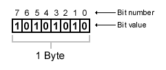
Bitmaps can come in different flavors. We differentiate bitmaps from each other by the amount of color information that is stored within them. We can have for example a bitmap that can only hold 2 distinct colors. We call this kind of bitmap a 1 bit bitmap because there’s only 1 bit per color needed to store the bitmap (these bitmaps are also known as black & white bitmaps). As you can see in figure 1, a byte can hold up to eight pixel values. The ‘1’ in the bit values means there’s a color (usually represented with white) and a ‘0’ in a bit value means there’s no color (usually represented with black). As you can imagine, there’s usually very little memory needed to store a black & white bitmap because a single byte can hold up to eight pixels.
Nowadays, black & white bitmaps are not used very much anymore. And especially not in high tech graphics programming (like games etc. although there is some usage for them, like in collision detection but that’s a whole different story which we won’t go into right now).
So, now we understand how black & white bitmaps work, now let’s take a look at what’s at the other side of the spectrum. True Color bitmaps. With True Color bitmaps we can represent far more colors than just the two represented with black & white bitmaps. With True Color bitmaps we can represent all the colors the human eye can see (that’s over 16 million). To store all those colors we’ll need a lot more space then that crammy little 1 bit used in black & white bitmaps. True Color bitmaps are usually represented with 24 bits per pixel, so it’s not even possible to store one pixel in one byte. We’re going to need three bytes to store only one pixel!
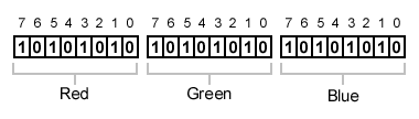
As you can see in figure 2, the 24 bits that make up our pixel are divided into three distinct components. We’ve got a red, green and blue component, each of them 8 bits wide. When each component is 8 bits wide it’s range can be 0 - 255, meaning that 0 is no color at all and 255 the brightest it can be. When the three components are set to 0 the pixel will be black. When the three components are set to 255 the pixel will be bright white.
Now that you understand black & white and True Color bitmaps we will discuss the in between formats. These formats are better known as the HiColor and indexed formats. To start with the indexed format, this format is probably the most used format, but that’s slowly going to change as True Color bitmaps take over the world with JPEG and other kinds. The bit depth of this format ranges from 1 to 8 bits on most popular video cards today and can hold 2 to 256 distinct colors chosen out of 16 million.
The reason why this format is called ‘indexed’ is because this format uses a Color LookUp Table (CLUT) to display it’s colors. The pixel value you write into memory corresponds with a RGB tripple in the CLUT as Figure 3 illustrates.
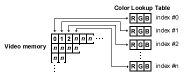
As you can see in Figure 3, the bytes in video memory corresponds with an index in the CLUT or better known as a palette. You can imagine that indexed formats can save a lot of memory. Instead of storing the same RGB value for a pixel over and over again it uses a simple indexing technique to represent colors. A down size to this technique is of course that the number of colors that can be displayed at once is limited (usually 256).
On the other hand, HiColor formats work with direct RGB values. Although the pixels are only stored in 15 or 16 bits, HiColor images can still look very realistic. HiColor formats can be best compared with True Color formats because of the way the pixel stores RGB information instead of using a CLUT like in indexed formats. A downside of using HiColor formats is of course the loss of color information when a HiColor image is displayed.
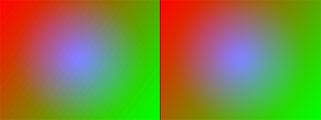
As you can see in Figure 4, the loss of color information can be noticed immediatly. On the left is a HiColor image and on the right the same image but in True Color. This is an artifact very common to HiColor images and when working with HiColor graphics you will have to take this into account. In the next paragraph it will become clear where this loss of color information comes from.
As said before, HiColor formats use 15 or 16 bits to represent a pixels color. Just like the 24 bits in the True Color format are broken down into three components the same thing counts for the HiColor format. The 15 or 16 bits of the HiColor pixel value are also broken down to three different components, one for red, green and blue. Because we have in HiColor 8 bits fewer to represent colors than in the True Color format we’ll have fewer bits to represent our red, green and blue.
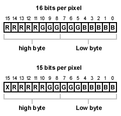
As you can see in Figure 5, for the 16 bit format the 16 bits are divided into groups. For the red component there are 5 bits reserved (bits 11-15). For the green component are 6 bits reserved (bits 5-10) and for the blue component, are just like the red component, are 5 bits reserved (bits 0-4). You my notice that the green component has 6 bits instead of 5 bits like the red en blue components. This is because the human eye is more sensitive to green than to red and blue. In the 15 bit format it works the same but for the green component only 5 bits are reserved and the most significant bit of the 16 bits is not used. Take a look again at figure 4 and look closely at the red and green parts of the left image. You may notice that the green part is less degraded than the red part. This is because this image was taken on 16 bits and for the green bits we’ve got one extra bit (6 instead of 5).
You may have figured out by now where this degradation of color comes from in the HiColor format. In True Color we’ve got far more bits to represent a component by than in HiColor. For example, the red component value 192 represented binary in 8 bits will be 11000000. The value 193 will be in binary 11000001. But, because we remove the lower three bits for the red component to fit it into only 5 bits, in HiColor both values will become the same (11000). So colors that may look different (and are different) in True Color may end up being the same in HiColor.
You may have noticed by now that I’ve not covered the 32 bits format. This is because there is no such format as 32 bits per pixel. When dealing with 32 bits per pixel we’re actually dealing with 24 bits per pixel but they are only stored in 32 bits. This is because computers can handle 32 bits of data more efficiently than 24 bits of data. One byte of the 32 bits color information is usually not used for color information. You can use this extra byte as an alpha value of as a z-buffer value.
So, now that we know the basic bitmap formats let’s move on to the DIB Section. As stated before, the DIB Section is a description of the bitmap. It tells Windows for example the width, height and color depth of our image. To create a DIB Section we need two structures that are defined in wingdi.h (you do not need to include this file yourself, it’s done for you when you include windows.h in your program). These two structures are BITMAPINFO and BITMAPINFOHEADER. Actually, you just need the BITMAPINFO structure, because the BITMAPINFOHEADER structure is included within the BITMAPINFO structure.
typedef struct tagBITMAPINFO { // bmi
    BITMAPINFOHEADER bmiHeader;
    RGBQUAD          bmiColors[1];
} BITMAPINFO;
As you can see above, this is how the BITMAPINFO structure is defined in wingdi.h. It contains a BITMAPINFOHEADER structure and one RGBQUAD structure. The BITMAPINFOHEADER is defined as follows:
typedef struct tagBITMAPINFOHEADER { // bmih
    DWORD	biSize;
    LONG	biWidth;
    LONG	biHeight;
    WORD	biPlanes;
    WORD	biBitCount
    DWORD	biCompression;
    DWORD	biSizeImage;
    LONG	biXPelsPerMeter;
    LONG	biYPelsPerMeter;
    DWORD	biClrUsed;
    DWORD	biClrImportant;
} BITMAPINFOHEADER;
The BITMAPINFOHEADER holds all the primary information of the DIB like width, height and color depth. Most of the members of this structure you can set to zero because they are not very important to us. Take for example the biXPelsPerMeter and biYPelsPerMeter. These members can be used for devices like printers and plotters (The reason why they are called Pels and not Pixels is because of IBM. When Microsoft developed the first version of OS/2 for IBM they had to play by their rules and IBM refers to Pixels as Pels. When Microsoft started to developing Windows, they left the name definitions intact according to the IBM format).
The other structure included in the BITMAPINFO structure is the RGBQUAD structure. This structure is one slot for one RGB color definition. This structure is only used for indexed formats and looks like this:
typedef struct tagRGBQUAD { // rgbq
    BYTE    rgbBlue;
    BYTE    rgbGreen;
    BYTE    rgbRed;
    BYTE    rgbReserved;
} RGBQUAD;
As you can see, this structure has four byte members. One for each color component red, green and blue and an extra reserved byte which you can leave set to zero. You may ask yourself why there’s only one RGBQUAD present in the BITMAPINFO structure? Most of this time you will need many more RGB tripples to define your palette. Well we’re actually not going to use the BITMAPINFO structure like it is stated here. We’re going to dynamically allocated memory for it and that way we have control over how many RGBQUAD’s we’re able to use. If we were about to allocate memory for a BITMAPINFO header for the use with a 256 color DIB we would have to allocate room for 256 RGBQUAD structures within it.
LPBITMAPINFO lpBmi;
lpBmi = (LPBITMAPINFO)malloc(sizeof(BITMAPINFO) + sizeof(RGBQUAD) * 256));
As you can see in the piece of code above, the malloc function allocates a block of memory. The size of this block of memory equals the size of the BITMAPINFO structure plus the size of 256 RGBQUAD structures.
Now that we have a BITMAPINFO structure allocated, we can start filling it with the right information. Let’s assume we continue with the creation of our 256 color DIB. We can now set some of the basic member variables of the BITMAPINFOHEADER.
lpBmi->bmiHeader.biSize = sizeof(BITMAPINFOHEADER);
lpBmi->bmiHeader.biWidth = DIB_WIDHT;
lpBmi->bmiHeader.biHeight = -(signed)DIB_HEIGHT;
lpBmi->bmiHeader.biPlanes = 1;
lpBmi->bmiHeader.biCompression = BI_RGB;
lpBmi->bmiHeader.biBitCount = 8;
lpBmi->bmiHeader.biSizeImage = 0;
lpBmi->bmiHeader.biXPelsPerMeter = 0;
lpBmi->bmiHeader.biYPelsPerMeter = 0;
lpBmi->bmiHeader.biClrUsed = 0;
lpBmi->bmiHeader.biClrImportant = 0;
As you can see, the first member we set is the biSize member of the BITMAPINFOHEADER. We have to set this member to the size of the structure because this is the way Windows does it’s version checking on structures. When Microsoft changes a structure (for example adds a new member to it) it’s size will also change. The second two members are the width and height of our DIB. This, as you already guessed, sets the width and height for our DIB. But notice something strange in setting the height value! Instead of setting it to DIB_HEIGHT it’s being set to -DIB_HEIGHT. What’s going on? Well, Windows uses a strange way of handling it’s DIB’s. Standard, DIB’s (and bitmaps) are so called "bottom-up". This means that the highest scanline within the bitmap is actually the lowest within the image. As scanlines progresses they travel upwards instead of downwards. Take a look at figure 6.
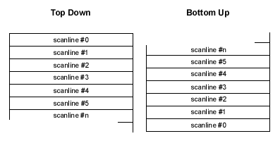
As you can see on the left, this is a normal situation. This is a Top Down DIB. But on the right side you’ll see a Bottom Up situation which it’s Windows default mode. To make sure the DIB is Top Down we’ll have to set it’s height value to a negative number. The reason why this is possible, i’m not sure at the time of this writing. Maybe there is some video hardware that works the other way around (building up it’s display image from bottom to top, I don’t know). Anyways, just try to remember this and I suggest you do some experimenting of your own with the height value so you can see it all for yourself.
After setting the width and the height for the DIB we set the number of planes for our DIB, its value should always equal 1. Then we can set the following important member of the BITMAPINFOHEADER, the biCompression member. There are a number of things you can do with this member. For us it is important that we have a linear bitmap, so we don’t need any compression at all. Later on, when working with HiColor and True Color DIB’s we will add an extra flag to the biCompression member, but for now just set it to BI_RGB. The last important member of the BITMAPINFOHEADER to set is the biBitCount. This member indicates the format of our DIB. Because we’re creating and 256 color bitmap (8 bits per pixel) in this example we’ll set this member to 8. The other members you can just set to zero, there’s no need to use them at this moment.
OK, now we’ve got the definition of our DIB ready, it’s time to initialize the palette for our DIB. Since we haven’t touched any of the RGB triplets in the palette, they’re probably containing some useless data. Let’s initialize the 256 RGBQUAD’s to a nice grayscale palette.
for(int i = 0; i < 256; i++) {
	lpBmi->bmiColors[i].rgbRed	= (BYTE)i;
	lpBmi->bmiColors[i].rgbGreen	= (BYTE)i;
	lpBmi->bmiColors[i].rgbBlue	= (BYTE)i;
	lpBmi->bmiColors[i].rgbReserved	= (BYTE)0;
}
So, now we have a complete description of our DIB. The only thing that’s left to do is allocating a block of memory which will represent our bitmap surface to which we can draw pixels.
BYTE* pBits = (BYTE*)malloc(DIB_WIDHT * DIB_HEIGHT);And it’s as simple as that.
We now have got ourselves a nice little DIB that we can display. Remember that when we were using normal bitmaps in an earlier section of this text we needed to select our bitmap into a DC first to be able to use the BitBlt function? With DIB’s we don’t need to do that any longer. There’s a special set of functions to display DIB’s on the screen. The first function is called SetDIBitsToDevice and the other function is called StretchDIBits. When using these functions these no need to select them into a DC first so that’s a little less overhead. Take a look a the following snippet of code:
SetDIBitsToDevice(
  hDC,			// Target DC
  0,			// Destination X-coord.
  0,			// Destination Y-coord.
  DIB_WIDTH,		// DIB width in pixels
  DIB_HEIGHT,		// DIB height in pixels
  0,			// Source X-coord.
  0,			// Source Y-coord.
  0,			// Starting scanline
  DIB_HEIGHT,		// Number of scanlines
  (BYTE*)pBits,		// Pointer to the DIB surface data
  lpBmi,		// Pointer to the BITMAPINFO struct.
  DIB_RGB_COLORS	// Display mode
);
As you can see, the SetDIBitsToDevice function takes a lot of parameters. The first parameter will be a handle to a DC of the target window (you usually get one in your OnPaint function or you can get it with GetDC). The second and third parameters set the x- and y-coordinates of the DIB to display it in the target DC. The fourth and fifth parameters set the width and height of the DIB. The seventh and eight parameter set the x- and y-coordinates of the source position within the DIB surface (usually you set these to zero). The ninth parameter indicates the starting scanline within the DIB and the tenth parameter indicates the number of scanlines of the DIB. The eleventh parameter is a pointer to the DIB surface data and the twelfth parameter a pointer to our allocated BITMAPINFO structure. The last parameter indicates our display mode and is usually set to DIB_RGB_COLORS.
So, now you will be able to create a 256 color DIB and display it in your application window. But what about HiColor and True Color DIB’s? Well, as you may have guessed, they are not the same so we have to do some different initialization on them. Let’s take look at initializing a 32 bit True Color DIB.
LPBITMAPINFO lpBmi;
lpBmi = (LPBITMAPINFO)malloc(sizeof(BITMAPINFO) + sizeof(DWORD) * 4);

lpBmi->bmiHeader.biSize = sizeof(BITMAPINFOHEADER);
lpBmi->bmiHeader.biWidth = DIB_WIDHT;
lpBmi->bmiHeader.biHeight = -(signed)DIB_HEIGHT;
lpBmi->bmiHeader.biPlanes = 1;
lpBmi->bmiHeader.biCompression = BI_RGB | BI_BITFIELDS;
lpBmi->bmiHeader.biBitCount = 32;
lpBmi->bmiHeader.biSizeImage = 0;
lpBmi->bmiHeader.biXPelsPerMeter = 0;
lpBmi->bmiHeader.biYPelsPerMeter = 0;
lpBmi->bmiHeader.biClrUsed = 0;
lpBmi->bmiHeader.biClrImportant = 0;
As you can see, this is not entirely the same as creating a 256 color DIB. The first thing that’s different is the allocation of the BITMAPINFO structure. As you may have noticed, the size that’s being allocated equals the size of a BITMAPINFO structure plus the size of four DWORD’s. When allocating a 256 color DIB we reserved 256 RGBQUAD’s of extra memory to hold the palette. But since a True Color DIB doesn’t have a palette, there’s no need to allocate memory for it. But what are those four DWORD’s for you may ask? Well, we will come to that in a second. The second thing that’s different for creating a 256 color DIB is the biCompression field. As you can see, this is no longer being set to BI_RGB only. It’s also set to BI_BITFIELDS. This has to do with those four DWORD’s again and we will discuss it later on. The only other thing that’s different from the 256 color DIB is the biBitCount member. This time it’s set to 32 (because we’re creating a 32 bits per pixel DIB).
OK, about those extra four DWORD’s. Why are they important to us? Well, they’re not very important to us, but they are important to Windows. You can if you will, leave these extra four DWORD’s of memory alone and things will probably still be running just fine. But, they are there for a purpose. Let me explain. Not all video boards are the same. As I tried to explain before in the basic’s of bitmap formats (previous section) I mentioned the fact that you can not always talk about RGB. Sometimes, some video boards use BGR instead or some other obscure format. So, we will have to let Windows know how our RGB components are constructed. Is it RGB or BGR or something different? That’s where those four extra DWORD’s come in. They are better known as the Bit Fields (hence the BI_BITFIELDS flag in the biCompression member). So what do we do with them? We fill ‘em up! Take a look at the example below:
DWORD *pBmi = (DWORD*)lpBmi->bmiColors;

pBmi[0] = 0x00FF0000;	// Red mask
pBmi[1] = 0x0000FF00;	// Green mask
pBmi[2] = 0x000000FF;	// Blue mask
pBmi[3] = 0x00000000;	// Not used (Alpha?)
In 32 bits per pixel our pixels are represented using a DWORD (4 bytes). Within that DWORD are our red, green and blue components stored in some kind of order. You can not always take for granted that it’s the same order on every video board, although most of the time it is. Take a look at figure 7, it shows two different kind of formats you can have in 32 bits per pixel. (The second one should read "Blue / Green / Red")
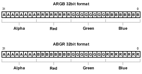
As you can see, the highest byte (the one on the left) is reserved for our Alpha value. But in both images it shows an example of RGB and BGR. We have to let Windows know where in the DWORD our red, green and blue values are stored. We do this by creating a mask. In the case of ARGB the red mask will be 0x00FF0000, the green mask will be 0x0000FF00 and the blue mask will be 0x000000FF. The same thing counts of course if we were to create a 15 or 16 bit DIB. The masks will look like this:
// masks for 15 bits per pixel
pBmi[0] = 0x00007C00;	// Red mask
pBmi[1] = 0x000003E0;	// Green mask
pBmi[2] = 0x0000001F;	// Blue mask
pBmi[3] = 0x00000000;	// Not used (Alpha?)

// masks for 16 bits per pixel
pBmi[0] = 0x0000F800;	// Red mask
pBmi[1] = 0x000007E0;	// Green mask
pBmi[2] = 0x0000001F;	// Blue mask
pBmi[3] = 0x00000000;	// Not used (Alpha?)
Only this time we give the masks for the RGB components within a WORD (16 bits). The funny thing is, in the case of a 24 bits per pixel DIB Windows doesn’t need any Bit Fields to know where it’s RGB components are stored. Windows assumes that they are always stored in a RGB format. Maybe that’s because in 24 bits per pixel mode you are always working with a stream of bytes. So, this is how we initialize a 24 bits per pixel DIB:
LPBITMAPINFO lpBmi;
lpBmi = (LPBITMAPINFO)malloc(sizeof(BITMAPINFO));

lpBmi->bmiHeader.biSize = sizeof(BITMAPINFOHEADER);
lpBmi->bmiHeader.biWidth = DIB_WIDHT;
lpBmi->bmiHeader.biHeight = -(signed)DIB_HEIGHT;
lpBmi->bmiHeader.biPlanes = 1;
lpBmi->bmiHeader.biCompression = BI_RGB;
lpBmi->bmiHeader.biBitCount = 24;
lpBmi->bmiHeader.biSizeImage = 0;
lpBmi->bmiHeader.biXPelsPerMeter = 0;
lpBmi->bmiHeader.biYPelsPerMeter = 0;
lpBmi->bmiHeader.biClrUsed = 0;
lpBmi->bmiHeader.biClrImportant = 0;
As you can see there’s no need to allocate any extra space for our Bit Fields and there’s also no need to initialize them. Just remember to set your biBitCount member to 24.
If you like, you can now take a look at Example 3. In this example I demonstrate the creation of a DIB and the use of StretchDIBits. In the OnCreate procedure I also write a pixel to the DIB surface, but that’s something I will explain in the following chapter.
In the previous section we created our own DIB, but with only a DIB we can’t do very much. We also want to be able to draw to our DIB in order to show something on its surface. Normally you would use GDI to draw to your bitmaps, but because the DIB isn’t attached to a DC we can not use GDI to draw to our DIB. If you want you can attach your DIB to a DC but if you want to use it that way, the whole process of creating your own DIB would not be necessary and you should use normal bitmaps instead. The reason why we want to write our own graphics routines is because we can make them as fast as possible. GDI offers a great deal of drawing functionality but it’s usually very slow. With using GDI only, you would never be able to create a game running at a speed of 40 frames per second (or you should use a very fast machine).
The basic thing of drawing to a DIB surface is very straight forward but you can make it as complex as you like, depending on the type of operations you would like to perform. You can for example, create a simple sprite blitting (bit blt) routine with just using linear sprites. But you can also create a more advanced sprite blitting routine with the use of RLE sprites and program the whole blitting routine in assembly language. In this chapter I’m just going to show you the basics of writing to your DIB surface, because I don’t know how complex you want to make your blitting routines. If you understand the basics you can take it from there and build your own advanced routines on top of the information given here.
When writing directly to our DIB surface we have to take a few things into account. The most important thing is the bit depth of our surface. When using GDI you normally don’t have to worry about these things, GDI will handle all the dirty work for you. This is one of the things that makes GDI slow for high-speed graphics programming. Depending on the bit depth of our DIB surface, we have to write different kinds of code. The code for example, to put a pixel in a 8 bit DIB surface would be different than the code for putting a pixel in a 32 bit DIB surface. This is because of the memory layout. When dealing with 8 bit DIB’s, our surface is built up out of a stream of bytes and when dealing with a 32 bit DIB our surface is built up out of a stream of DWORDS. If the DIB’s width and height are the same for an 8 bit and 32 bit DIB, the 32 bit DIB would use four times the amount of memory over the 8 bit DIB. Let’s take a look at an example of a routine to write a pixel to the DIB surface:
void PutPixel(int x, int y, int color, void* pSurface)
{
	int offset = y * DIB_WIDTH + x;
	pSurface[offset] = color;
}
This code will actually not make it through your compiler because of the void*. I will try to explain how this code works and how it can make it through the compiler. First we have to understand the first line: int offset = y * DIB_WIDTH + x;. In reality computers do not understand what a x- and y-axis is. It only understands that is has some block of memory and that it can place values into the bytes that makeup that block of memory. In fact, when we look at an image on the computer display we see it has a dimension, like a width and height. But to your computer the image in memory is just one big stream of data with a beginning and an ending.

As you can see in figure 8, the image is just one big stream of data. But that stream of data is buildup out of the information of our scanlines. Let’s assume for example that our DIB is 320 pixel wide and 240 pixels in height. If we want to display a pixel in the middle of our DIB’s surface we will have to calculate an offset to the position of that pixel. The first thing we must do then is to calculate the scanline on which our pixel will be displayed. Since we know our DIB is 320 pixel wide then we can also assume one scanline of our DIB is 320 pixels wide. We would have to move our pointer to the scanline of our pixel by 320 times the y-axis of our pixel, 320 * y. The only thing that’s left to do is adding the x-axis to the offset and where done. So, to put a pixel in the middle of our DIB surface the formula will be:
offset = DIB_WIDTH * (DIB_HEIGHT / 2) + (DIB_WIDTH / 2)So again, the part DIB_WIDTH * (DIB_HEIGHT / 2) calculates the starting scanline and the (DIB_WIDTH / 2) part calculates the center point of that scanline.
So, now we know how to calculate an offset let’s look at the different bit depths again of plotting a pixel on the DIB surface. When dealing with a 8 bit DIB, the surface is buildup out of bytes. The pointer to our surface data would then be of course a BYTE*. Take a look at the following code:
void PutPixel(int x, int y, BYTE color, BYTE* pSurface)
{
	int offset = y * DIB_WIDTH + x;
	pSurface[offset] = color;
}
This piece of code will make it through the compiler. The pointer to our surface is of type BYTE* and the color parameter is of type BYTE. This code will actually work. Now let’s take a look at the code for plotting a pixel on a 32 bit surface:
void PutPixel(int x, int y, DWORD color, DWORD* pSurface)
{
	int offset = y * DIB_WIDTH + x;
	pSurface[offset] = color;
}
As you can see, the types of both the color parameter and the pSurface parameter are both changed to DWORD and DWORD*. For the rest of the code, there’s nothing changed. Calculating the offset and storing the pixel value into memory stays the same. The compiler takes care of all the dirty work for us here. It knows that when we’re dealing with a BYTE* it’s offset (pSurface[offset]) is in byte order. But when dealing with a DWORD* it knows it has to multiply the offset value by four (a DWORD is four times as large as a BYTE). By now you can take a look at Example 4. This program will demonstrate a pixel plot routine called PutPixel. I know this routine does not demonstrates the most efficient piece code possible but I hope it may clarify things a bit more.