(Tested on PineDio Stack BL604)
Read the article...
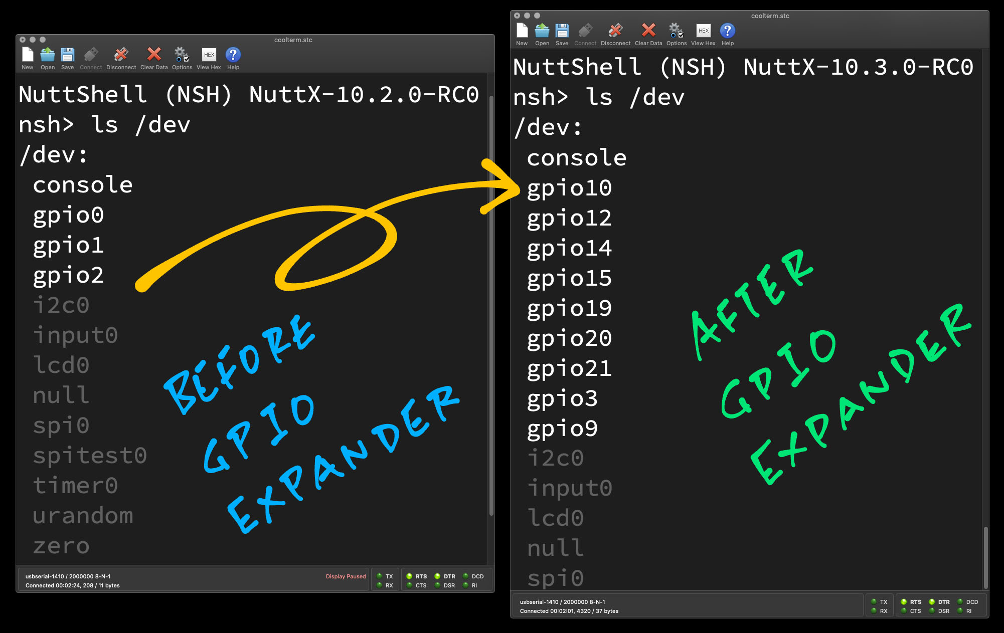
PineDio Stack BL604 has an interesting problem on Apache NuttX RTOS... Too many GPIOs! Let's make it work.
GPIO Expander exposes GPIOs 0 to 22 as /dev/gpio0 to /dev/gpio22, for easier development of NuttX Apps for PineDio Stack BL604.
GPIO Expander calls bl602_configgpio, bl602_gpioread and bl602_gpiowrite to configure / read / write GPIOs
Warning: BL602 EVB GPIO Driver will be disabled when we enable GPIO Expander.
(Because GPIO Expander needs GPIO Lower Half which conflicts with BL602 EVB GPIO Driver)
GPIO Expander verifies that the GPIO, SPI, I2C and UART Pins don't reuse the same GPIO.
Robert Lipe has an excellent article that explains the current limitations of the BL602 EVB GPIO Driver (and why we need the GPIO Expander)...
-
Tested OK with GPIO Interrupts from Touch Panel and LVGL Test App
lvgltest(With
IOEP_ATTACHincst816s_register) -
Tested OK with Push Button
(With
IOEP_ATTACHinbl602_bringup) -
Tested OK with Push Button GPIO Command:
gpio -t 8 -w 1 /dev/gpio12(Comment out
IOEP_ATTACHinbl602_bringup) -
Tested OK with LoRaWAN Test App
lorawan_test(With "GPIO Informational Output" logging disabled)
-
SX1262 Library is now configured by Kconfig / menuconfig to access
/dev/gpio10,/dev/gpio15,/dev/gpio19(instead ofdev/gpio0,/dev/gpio1,/dev/gpio2).In menuconfig: Library Routines → Semtech SX1262 Library
- SPI Test device path
- Chip Select device path
- Busy device path
- DIO1 device path
-
Logging for SX1262 Library is now disabled by default and can be configured by Kconfig / menuconfig.
In menuconfig: Library Routines → Semtech SX1262 Library → Logging → Debugging
-
Logging for SPI Test Driver has been moved from "Enable Informational Debug Output" to "SPI Informational Output"
TODO: GPIO Expander will check that the SPI / I2C / UART Pin Functions are correctly defined (e.g. MISO vs MOSI)
If you're using NuttX on PineDio Stack, there's no need to install the driver...
Otherwise to add this repo to your NuttX project...
pushd nuttx/nuttx/drivers/ioexpander
git submodule add https://github.com/lupyuen/bl602_expander
ln -s bl602_expander/bl602_expander.c .
popd

pushd nuttx/nuttx/include/nuttx/ioexpander
ln -s ../../../drivers/ioexpander/bl602_expander/bl602_expander.h .
popd
Next update the Makefile and Kconfig...
Then update the NuttX Build Config...
## TODO: Change this to the path of our "incubator-nuttx" folder
cd nuttx/nuttx

## Preserve the Build Config
cp .config ../config

## Erase the Build Config and Kconfig files
make distclean

## For PineDio Stack BL604: Configure the build for BL604
./tools/configure.sh bl602evb:pinedio

## For BL602: Configure the build for BL602
./tools/configure.sh bl602evb:nsh

## For ESP32: Configure the build for ESP32.
## TODO: Change "esp32-devkitc" to our ESP32 board.
./tools/configure.sh esp32-devkitc:nsh

## Restore the Build Config
cp ../config .config

## Edit the Build Config
make menuconfig
In menuconfig, enable the BL602 GPIO Expander under "Device Drivers → IO Expander/GPIO Support → Enable IO Expander Support".
Set "Number of pins" to 23.
Enable "GPIO Lower Half".
Edit the function bl602_bringup in this file...
nuttx/boards/risc-v/bl602/bl602evb/src/bl602_bringup.c
And call bl602_expander_initialize to initialise our driver, just after bl602_gpio_initialize:
#ifdef CONFIG_IOEXPANDER_BL602_EXPANDER
#include <nuttx/ioexpander/gpio.h>
#include <nuttx/ioexpander/bl602_expander.h>
FAR struct ioexpander_dev_s *bl602_expander = NULL;
#endif /* CONFIG_IOEXPANDER_BL602_EXPANDER */
...
int bl602_bringup(void) {
  ...
  /* Existing Code */

#if defined(CONFIG_DEV_GPIO) && !defined(CONFIG_GPIO_LOWER_HALF)
  ret = bl602_gpio_initialize();
  if (ret < 0)
    {
      syslog(LOG_ERR, "Failed to initialize GPIO Driver: %d\n", ret);
      return ret;
    }
#endif

  /* New Code */

#ifdef CONFIG_IOEXPANDER_BL602_EXPANDER
  /* Must load BL602 GPIO Expander before other drivers */

  bl602_expander = bl602_expander_initialize(
    bl602_gpio_inputs,
    sizeof(bl602_gpio_inputs) / sizeof(bl602_gpio_inputs[0]),
    bl602_gpio_outputs,
    sizeof(bl602_gpio_outputs) / sizeof(bl602_gpio_outputs[0]),
    bl602_gpio_interrupts,
    sizeof(bl602_gpio_interrupts) / sizeof(bl602_gpio_interrupts[0]),
    bl602_other_pins,
    sizeof(bl602_other_pins) / sizeof(bl602_other_pins[0]));
  if (bl602_expander == NULL)
    {
      syslog(LOG_ERR, "Failed to initialize GPIO Expander\n");
      return -ENOMEM;
    }
#endif /* CONFIG_IOEXPANDER_BL602_EXPANDER */
To validate the GPIOs at startup, all GPIOs shall be listed in bl602_gpio_inputs, bl602_gpio_outputs, bl602_gpio_interrupts and bl602_other_pins...
#ifdef CONFIG_IOEXPANDER_BL602_EXPANDER
/* GPIO Input Pins for BL602 GPIO Expander */

static const gpio_pinset_t bl602_gpio_inputs[] =
{
#ifdef BOARD_SX1262_BUSY
  BOARD_SX1262_BUSY,
#endif  /* BOARD_SX1262_BUSY */
...
};

/* GPIO Output Pins for BL602 GPIO Expander */

static const gpio_pinset_t bl602_gpio_outputs[] =
{
#ifdef BOARD_LCD_CS
  BOARD_LCD_CS,
#endif  /* BOARD_LCD_CS */
...
};

/* GPIO Interrupt Pins for BL602 GPIO Expander */

static const gpio_pinset_t bl602_gpio_interrupts[] =
{
#ifdef BOARD_TOUCH_INT
  BOARD_TOUCH_INT,
#endif  /* BOARD_TOUCH_INT */
...
};

/* Other Pins for BL602 GPIO Expander (For Validation Only) */

static const gpio_pinset_t bl602_other_pins[] =
{
#ifdef BOARD_UART_0_RX_PIN
  BOARD_UART_0_RX_PIN,
#endif  /* BOARD_UART_0_RX_PIN */
...
};
#endif /* CONFIG_IOEXPANDER_BL602_EXPANDER */We must load the GPIO Expander before other drivers (e.g. CST816S Touch Panel), because GPIO Expander provides GPIO functions for the drivers.
We need to disable BL602 GPIO Driver when we enable GPIO Expander, because GPIO Expander needs GPIO Lower Half which can't coexist with BL602 GPIO Driver:
/* Add CONFIG_GPIO_LOWER_HALF */
#if defined(CONFIG_DEV_GPIO) && !defined(CONFIG_GPIO_LOWER_HALF)
ret = bl602_gpio_initialize();To handle the GPIO Interrupt that's triggered when we press the Push Button...
#include <nuttx/ioexpander/gpio.h>
#include <nuttx/ioexpander/bl602_expander.h>
...
/* Get the Push Button Pinset and GPIO */

gpio_pinset_t pinset = BOARD_BUTTON_INT;
uint8_t gpio_pin = (pinset & GPIO_PIN_MASK) >> GPIO_PIN_SHIFT;

/* Configure GPIO interrupt to be triggered on falling edge */

DEBUGASSERT(bl602_expander != NULL);
IOEXP_SETOPTION(bl602_expander, gpio_pin, IOEXPANDER_OPTION_INTCFG,
                (FAR void *)IOEXPANDER_VAL_FALLING);

/* Attach GPIO interrupt handler */

void *handle = IOEP_ATTACH(bl602_expander,
                           (ioe_pinset_t)1 << gpio_pin,
                           button_isr_handler,
                           NULL);  //  TODO: Set the callback argument
DEBUGASSERT(handle != NULL);The Button Interrupt Handler button_isr_handler is defined as...
static int button_isr_handler(FAR struct ioexpander_dev_s *dev,
                              ioe_pinset_t pinset, FAR void *arg)
{
  gpioinfo("Button Pressed\n");
  return 0;
}Let's talk about how we created the BL602 GPIO Expander...
The NuttX GPIO Driver for BL602 EVB supports one GPIO Input, one GPIO Output and one GPIO Interrupt ... And names them sequentially: "/dev/gpio0", "/dev/gpio1", "/dev/gpio2"
Which can be super confusing because "/dev/gpio0" doesn't actually map to BL602 GPIO Pin 0.
("/dev/gpio0" maps to BL602 GPIO Pin 10)
("/dev/gpio1" maps to BL602 GPIO Pin 15)
("/dev/gpio2" maps to BL602 GPIO Pin 19)
What happens when we try to support 23 GPIOs on PineDio Stack BL604? Yep the GPIO Names will look really messy on NuttX.
All 23 GPIOs on PineDio Stack BL604 are wired up. Let's simplify NuttX and name the GPIOs as "/dev/gpio0" to "/dev/gpio22".
(So that "/dev/gpioN" will map to BL602 GPIO Pin N)
Easier for devs to create new NuttX Drivers!
NuttX lets us create I/O Expander Drivers that will handle many GPIOs (Input / Output / Interrupt). Perfect for PineDio Stack BL604!
Apache NuttX RTOS helpfully provides a Skeleton Driver for I/O Expander. Let's flesh it out for PineDio Stack BL604's GPIO Expander...
Other microcontrollers might also need a GPIO Expander. Like CH32V307, which has 80 GPIOs (!)
Our NuttX GPIO Expander implements the operations to: 1️⃣ Config / Read / Write GPIOs 2️⃣ Attach / Detach GPIO Interrupt Handlers 3️⃣ Handle GPIO Interrupts...
/* I/O Expander Operations */

static const struct ioexpander_ops_s g_bl602_expander_ops =
{
  bl602_expander_direction,
  bl602_expander_option,
  bl602_expander_writepin,
  bl602_expander_readpin,
  bl602_expander_readbuf
#ifdef CONFIG_IOEXPANDER_MULTIPIN
  , bl602_expander_multiwritepin
  , bl602_expander_multireadpin
  , bl602_expander_multireadbuf
#endif
#ifdef CONFIG_IOEXPANDER_INT_ENABLE
  , bl602_expander_attach
  , bl602_expander_detach
#endif
};We'll cover these operations below.
GPIO Interrupt Handling gets tricky for PineDio Stack BL604: All GPIO Interrupts are multiplexed into a single IRQ. Our GPIO Expander can help.
Here's the existing code for BL602 EVB that attaches a GPIO Interrupt Handler...
static int gpint_attach(struct gpio_dev_s *dev, pin_interrupt_t callback)
{
  struct bl602_gpint_dev_s *bl602xgpint =
    (struct bl602_gpint_dev_s *)dev;

  uint8_t gpio_pin =
    (g_gpiointinputs[bl602xgpint->bl602gpio.id] & GPIO_PIN_MASK) >>
    GPIO_PIN_SHIFT;
  gpioinfo("Attaching the callback\n");

  /* Make sure the interrupt is disabled */

  bl602xgpint->callback = callback;
  bl602_gpio_intmask(gpio_pin, 1);

  irq_attach(BL602_IRQ_GPIO_INT0, bl602_gpio_interrupt, dev);
  bl602_gpio_intmask(gpio_pin, 0);

  gpioinfo("Attach %p\n", callback);
  return OK;
}Note that all GPIO Interrupts are multiplexed into a single IRQ: BL602_IRQ_GPIO_INT0
When handling GPIO Interrupts, our GPIO Expander needs to demultiplex the BL602_IRQ_GPIO_INT0 IRQ into multiple GPIO Interrupts.
As noted (eloquently) by Robert Lipe, attaching a BL602 GPIO Interrupt Handler is hard (because our stars are misaligned)...
Let's fix this with our GPIO Expander for Apache NuttX RTOS.
Now With BL602 GPIO Expander, here's how we handle the GPIO Interrupt that's triggered when we press the Push Button on PineDio Stack...
#include <nuttx/ioexpander/gpio.h>
#include <nuttx/ioexpander/bl602_expander.h>
...
//  Get the Push Button Pinset and GPIO
gpio_pinset_t pinset = BOARD_BUTTON_INT;
uint8_t gpio_pin = (pinset & GPIO_PIN_MASK) >> GPIO_PIN_SHIFT;

//  Configure GPIO interrupt to be triggered on falling edge
DEBUGASSERT(bl602_expander != NULL);
IOEXP_SETOPTION(
  bl602_expander,  //  BL602 GPIO Expander
  gpio_pin,        //  GPIO Pin
  IOEXPANDER_OPTION_INTCFG,            //  Configure interrupt trigger
  (FAR void *) IOEXPANDER_VAL_FALLING  //  Trigger on falling edge
);

//  Attach GPIO interrupt handler
void *handle = IOEP_ATTACH(
  bl602_expander,                //  BL602 GPIO Expander
  (ioe_pinset_t) 1 << gpio_pin,  //  GPIO Pin converted to Pinset
  button_isr_handler,            //  GPIO Interrupt Handler
  NULL                           //  TODO: Set the callback argument
);
DEBUGASSERT(handle != NULL);Much easier now! The Button Interrupt Handler button_isr_handler is defined as...
static int button_isr_handler(FAR struct ioexpander_dev_s *dev, ioe_pinset_t pinset, FAR void *arg) {
  gpioinfo("Button Pressed\n");
  return 0;
}Note that the Button Interrupt Handler runs in the context of the Interrupt Handler. Be careful!
Another way to test the Push Button Interrupt is to use the GPIO Command...
nsh> gpio -t 8 -w 1 /dev/gpio12
Driver: /dev/gpio12
gplh_enable: pin12: Disabling callback=0 handle=0
gplh_enable: WARNING: pin12: Already detached
bl602_expander_option: pin=12, option=2, value=0x6
bl602_expander_option: Rising edge: pin=12
bl602_expander_set_intmod: gpio_pin=12, int_ctlmod=1, int_trgmod=1
gplh_read: pin12: value=0x42021aef
bl602_expander_readpin: pin=12, value=1
  Interrupt pin: Value=1
gplh_attach: pin12: callback=0x23060808
gplh_enable: pin12: Enabling callback=0x23060808 handle=0
gplh_enable: pin12: Attaching 0x23060808
bl602_expander_attach: pinset=1000, callback=0x2305f4e2, arg=0x42020d40
bl602_expander_attach: Attach callback for gpio=12, callback=0x2305f4e2, arg=0x42020d40
bl602_expander_interrupt: Interrupt! context=0x42012db8, priv=0x4201d0f0
bl602_expander_interrupt: Call gpio=12, callback=0x2305f4e2, arg=0x42020d40
gplh_handler: pin12: pinset: c callback=0x23060808
gplh_enable: pin12: Disabling callback=0x23060808 handle=0x4201d1a0
gplh_enable: pin12: Detaching handle=0x4201d1a0
bl602_expander_detach: Detach callback for gpio=12, callback=0x2305f4e2, arg=0x42020d40
gplh_attach: pin12: callback=0
gplh_read: pin12: value=0x42021aef
bl602_expander_readpin: pin=12, value=1
  Verify:        Value=1
But this works only if we don't call IOEP_ATTACH to attach the Interrupt Handler.
The CST816S Driver for PineDio Stack's Touch Panel now calls BL602 GPIO Expander to attach the GPIO Interrupt Handler...
//  Register the CST816S device (e.g. /dev/input0)
int cst816s_register(FAR const char *devpath, FAR struct i2c_master_s *i2c_dev, uint8_t i2c_devaddr) {
  ...
  //  Configure GPIO interrupt to be triggered on falling edge
  DEBUGASSERT(bl602_expander != NULL);
  IOEXP_SETOPTION(
    bl602_expander,  //  BL602 GPIO Expander
    gpio_pin,        //  GPIO Pin
    IOEXPANDER_OPTION_INTCFG,            //  Configure interrupt trigger
    (FAR void *) IOEXPANDER_VAL_FALLING  //  Trigger on falling edge
  );

  //  Attach GPIO interrupt handler
  handle = IOEP_ATTACH(
    bl602_expander,                //  BL602 GPIO Expander
    (ioe_pinset_t) 1 << gpio_pin,  //  GPIO Pin converted to Pinset
    cst816s_isr_handler,  //  GPIO Interrupt Handler
    priv                  //  Callback argument
  );
  if (handle == NULL) {
    kmm_free(priv);
    ierr("Attach interrupt failed\n");
    return -EIO;
}The functions for configuring and handling GPIO Interrupts have been moved from the CST816S Driver to BL602 GPIO Expander.
The Semtech SX1262 LoRa Transceiver on PineDio Stack triggers a GPIO Interrupt (on pin DIO1) when a LoRa packet is transmitted or received.
Here's the existing code that configures the GPIO Interrupt and attaches the Interrupt Handler...
/// Init the GPIO Pins. Return 0 on success.
static int init_gpio(void) {
  ...
  //  Open GPIO Interrupt for SX1262 DIO1 Pin
  dio1 = open(DIO1_DEVPATH, O_RDWR);
  assert(dio1 > 0);

  //  Get SX1262 DIO1 Pin Type
  ret = ioctl(dio1, GPIOC_PINTYPE, (unsigned long)((uintptr_t)&pintype));
  assert(ret >= 0);

  //  Verify that SX1262 DIO1 Pin is GPIO Interrupt (not GPIO Input or GPIO Output)
  assert(pintype == GPIO_INTERRUPT_PIN);

  //  Change DIO1 Pin to Trigger GPIO Interrupt on Rising Edge
  //  TODO: Crashes at ioexpander/gpio.c (line 544) because change failed apparently
  ret = ioctl(dio1, GPIOC_SETPINTYPE, (unsigned long) GPIO_INTERRUPT_RISING_PIN);
  assert(ret >= 0);
  ...
  //  Start the Background Thread to process DIO1 interrupts
  static pthread_t thread;
  ret = pthread_create(&thread, &attr, process_dio1, 0);
assert(ret == 0);This code calls ioctl() in the User Space (instead of Kernel Space), so it works OK with BL602 GPIO Expander without modification.
(Because ioctl() calls the GPIO Lower Half Driver, which is integrated with our BL602 GPIO Expander)
For PineDio Stack, we changed the definition of DIO1_DEVPATH to "/dev/gpio19"...
CONFIG_LIBSX1262_SPI_DEVPATH="/dev/spitest0"
CONFIG_LIBSX1262_CS_DEVPATH="/dev/gpio15"
CONFIG_LIBSX1262_BUSY_DEVPATH="/dev/gpio10"
CONFIG_LIBSX1262_DIO1_DEVPATH="/dev/gpio19"
For backward compatibility with BL602 (which doesn't use GPIO Expander), we default DIO1_DEVPATH to "/dev/gpio2" if DIO1_DEVPATH isn't configured...
#ifdef CONFIG_LIBSX1262_DIO1_DEVPATH
#define DIO1_DEVPATH CONFIG_LIBSX1262_DIO1_DEVPATH
#else
#define DIO1_DEVPATH "/dev/gpio2"
#endif // CONFIG_LIBSX1262_DIO1_DEVPATHTracking all 23 GPIOs used by PineDio Stack BL604 can get challenging... We might reuse GPIOs by mistake! Our BL602 GPIO Expander shall validate the GPIOs at startup.
Here are the GPIOs currently defined for PineDio Stack...
At startup, GPIO Expander verifies that the GPIO, SPI, I2C and UART Pins don't reuse the same GPIO.
If GPIOs are reused in board.h...
#define BOARD_SPI_CLK  (GPIO_INPUT | GPIO_PULLUP | GPIO_FUNC_SPI | GPIO_PIN11)
...
#define BOARD_BUTTON_INT (GPIO_INPUT | GPIO_FLOAT | GPIO_FUNC_SWGPIO | GPIO_PIN11)
Then GPIO Expander will halt with an error at startup...
bl602_expander_option: pin=11, option=2, value=0xe
bl602_expander_option: Unsupported interrupt both edge: pin=11
gplh_enable: pin11: Disabling callback=0 handle=0
gplh_enable: WARNING: pin11: Already detached
gpio_pin_register: Registering /dev/gpio11
...
bl602_expander_initialize: ERROR: GPIO pin 11 is already in use
up_assert: Assertion failed at file:mm_heap/mm_free.c line: 102 task: nsh_main
We implement this by listing all GPIOs in bl602_gpio_inputs, bl602_gpio_outputs, bl602_gpio_interrupts and bl602_other_pins...
#ifdef CONFIG_IOEXPANDER_BL602_EXPANDER
//  GPIO Input Pins for BL602 GPIO Expander
static const gpio_pinset_t bl602_gpio_inputs[] =
{
#ifdef BOARD_SX1262_BUSY
  BOARD_SX1262_BUSY,
#endif  /* BOARD_SX1262_BUSY */
...
};

//  GPIO Output Pins for BL602 GPIO Expander
static const gpio_pinset_t bl602_gpio_outputs[] =
{
#ifdef BOARD_LCD_CS
  BOARD_LCD_CS,
#endif  /* BOARD_LCD_CS */
...
};

//  GPIO Interrupt Pins for BL602 GPIO Expander
static const gpio_pinset_t bl602_gpio_interrupts[] =
{
#ifdef BOARD_TOUCH_INT
  BOARD_TOUCH_INT,
#endif  /* BOARD_TOUCH_INT */
...
};

//  Other Pins for BL602 GPIO Expander (For Validation Only)
static const gpio_pinset_t bl602_other_pins[] =
{
#ifdef BOARD_UART_0_RX_PIN
  BOARD_UART_0_RX_PIN,
#endif  /* BOARD_UART_0_RX_PIN */
...
};
#endif /* CONFIG_IOEXPANDER_BL602_EXPANDER */At startup, GPIO Expander verifies that the GPIOs are not reused...
FAR struct ioexpander_dev_s *bl602_expander_initialize(
  const gpio_pinset_t *gpio_inputs,     uint8_t gpio_input_count,
  const gpio_pinset_t *gpio_outputs,    uint8_t gpio_output_count,
  const gpio_pinset_t *gpio_interrupts, uint8_t gpio_interrupt_count,
  const gpio_pinset_t *other_pins,      uint8_t other_pin_count) {
  ...
  //  Mark the GPIOs in use
  bool gpio_is_used[CONFIG_IOEXPANDER_NPINS];
  memset(gpio_is_used, 0, sizeof(gpio_is_used));

  //  Validate the GPIO Inputs
  for (i = 0; i < gpio_input_count; i++) {
    //  Get GPIO Pinset and GPIO Pin Number
    gpio_pinset_t pinset = gpio_inputs[i];
    uint8_t gpio_pin = (pinset & GPIO_PIN_MASK) >> GPIO_PIN_SHIFT;

    //  Check that the GPIO is not in use
    DEBUGASSERT(gpio_pin < CONFIG_IOEXPANDER_NPINS);
    if (gpio_is_used[gpio_pin]) {
      gpioerr("ERROR: GPIO pin %d is already in use\n", gpio_pin);
      return NULL;
    }
    gpio_is_used[gpio_pin] = true;
  }

// Omitted: Validate the GPIO Outputs, GPIO Interrupts and Other PinsIn future, our BL602 GPIO Expander will validate that the SPI / I2C / UART Pin Functions are correctly assigned to the GPIO Pin Numbers...
For example: SPI MISO must be either GPIO 0, 4, 8, 12, 16 or 20.
Any other GPIO Pin for SPI MISO will be disallowed by our BL602 GPIO Expander. (And fail at startup)
But the BL602 Pinset only tells us the Function Group (like SPI), not the specific Pin Function (like MISO)?
Yeah we might have to make the Pin Functions position-dependent. So SPI Pins will always be listed in this sequence: CS, MOSI, MISO, then CLK.
Here's how it might look...
/* Other Pins for BL602 GPIO Expander (For Validation Only) */

static const gpio_pinset_t bl602_other_pins[] =
{
#ifdef BOARD_UART_0_RX_PIN
  RX_TX
  (
    BOARD_UART_0_RX_PIN,
    BOARD_UART_0_TX_PIN
  ),
#endif  /* BOARD_UART_0_RX_PIN */

#ifdef BOARD_UART_1_RX_PIN
  RX_TX
  (
    BOARD_UART_1_RX_PIN,
    BOARD_UART_1_TX_PIN
  ),
#endif  /* BOARD_UART_1_RX_PIN */

#ifdef BOARD_PWM_CH0_PIN
  CH(
    BOARD_PWM_CH0_PIN
  ),
#endif  /* BOARD_PWM_CH0_PIN */
...
#ifdef BOARD_I2C_SCL
  SCL_SDA
  (
    BOARD_I2C_SCL,
    BOARD_I2C_SDA
  ),
#endif  /* BOARD_I2C_SCL */

#ifdef BOARD_SPI_CS
  CS_MOSI_MISO_CLK
  (
    BOARD_SPI_CS,
    BOARD_SPI_MOSI,
    BOARD_SPI_MISO,
    BOARD_SPI_CLK
  ),
#endif  /* BOARD_SPI_CS */
};
(Which looks neater with the clustering by Function Group)
The macros are simple passthroughs...
#define CH(ch)            ch
#define RX_TX(rx, tx)     rx,  tx
#define SCL_SDA(scl, sda) scl, sda
#define CS_MOSI_MISO_CLK(cs, mosi, miso, clk) cs, mosi, miso, clk
At startup, GPIO Expander iterates through the pins and discovers that BOARD_SPI_MISO is the third pin (MISO) of the SPI Function Group. So it verifies that it's either GPIO 0, 4, 8, 12, 16 or 20.
Are devs OK with this? Lemme know what you think!
Can we validate the Pin Functions at compile-time?
Possibly. We can enumerate all valid combinations of Pin Functions and Pin Numbers...
//  MISO can be either GPIO 0, 4, 8, 12, 16 or 20
#define SPI_MISO_PIN0  (GPIO_INPUT | GPIO_PULLUP | GPIO_FUNC_SPI | GPIO_PIN0)
#define SPI_MISO_PIN4  (GPIO_INPUT | GPIO_PULLUP | GPIO_FUNC_SPI | GPIO_PIN4)
#define SPI_MISO_PIN8  (GPIO_INPUT | GPIO_PULLUP | GPIO_FUNC_SPI | GPIO_PIN8)
#define SPI_MISO_PIN12 (GPIO_INPUT | GPIO_PULLUP | GPIO_FUNC_SPI | GPIO_PIN12)
#define SPI_MISO_PIN16 (GPIO_INPUT | GPIO_PULLUP | GPIO_FUNC_SPI | GPIO_PIN16)
#define SPI_MISO_PIN20 (GPIO_INPUT | GPIO_PULLUP | GPIO_FUNC_SPI | GPIO_PIN20)
And we select the desired combination for each pin...
//  Select GPIO0 as MISO
#define BOARD_SPI_MISO SPI_MISO_PIN0
To check whether the Pin Numbers are unique, we would still need GPIO Expander to do this at runtime.
But shouldn't the pins be defined in Kconfig / menuconfig?
Perhaps. NuttX on ESP32 uses Kconfig / menuconfig to define the pins. (See this)
Then we would need GPIO Expander to validate the Pin Functions at runtime.
@Ralim has an interesting suggestion...
If each pin can only be used once, could we flip the arrignment matrix and instead have it always have an entry for each pin, which is either a selected value or hi-z by default; then use kconfig rules to prevent collisions ?
Which raises the question: Shouldn't we do the same for NuttX on ESP32? What about other NuttX platforms? 🤔
At startup our BL602 GPIO Expander configures the GPIO Input / Output / Interrupt Pins by calling bl602_configgpio and gpio_lower_half (which registers "/dev/gpioN")...
//  Initialise the BL602 GPIO Expander
FAR struct ioexpander_dev_s *bl602_expander_initialize(
  const gpio_pinset_t *gpio_inputs,
  uint8_t gpio_input_count,
  const gpio_pinset_t *gpio_outputs,
  uint8_t gpio_output_count,
  const gpio_pinset_t *gpio_interrupts,
  uint8_t gpio_interrupt_count,
  const gpio_pinset_t *other_pins,
  uint8_t other_pin_count)
{
  int i;
  int ret;
  uint8_t pin;
  bool gpio_is_used[CONFIG_IOEXPANDER_NPINS];
  FAR struct bl602_expander_dev_s *priv;

  DEBUGASSERT(gpio_input_count + gpio_output_count + gpio_interrupt_count +
    other_pin_count <= CONFIG_IOEXPANDER_NPINS);

#ifdef CONFIG_BL602_EXPANDER_MULTIPLE
  /* Allocate the device state structure */

  priv = (FAR struct bl602_expander_dev_s *)kmm_zalloc(sizeof(struct bl602_expander_dev_s));
  if (!priv)
    {
      gpioerr("ERROR: Failed to allocate driver instance\n");
      return NULL;
    }
#else
  /* Use the one-and-only I/O Expander driver instance */

  priv = &g_skel;
#endif

  /* Initialize the device state structure */

  priv->dev.ops = &g_bl602_expander_ops;
  nxsem_init(&priv->exclsem, 0, 1);

#ifdef CONFIG_IOEXPANDER_INT_ENABLE
  /* Disable GPIO interrupts */

  ret = bl602_expander_irq_enable(false);
  if (ret < 0)
    {
      gpioerr("ERROR: Failed to disable GPIO interrupts\n");
      kmm_free(priv);
      return NULL;
    }

  /* Disable interrupts for all GPIO Pins */

  for (pin = 0; pin < CONFIG_IOEXPANDER_NPINS; pin++)
    {
      bl602_expander_intmask(pin, 1);
    }

  /* Attach the I/O expander interrupt handler and enable interrupts */

  irq_attach(BL602_IRQ_GPIO_INT0, bl602_expander_interrupt, priv);

  ret = bl602_expander_irq_enable(true);
  if (ret < 0)
    {
      gpioerr("ERROR: Failed to enable GPIO interrupts\n");
      kmm_free(priv);
      return NULL;
    }
#endif

  /* Mark the GPIOs in use */

  memset(gpio_is_used, 0, sizeof(gpio_is_used));

  /* Configure and register the GPIO Inputs */

  for (i = 0; i < gpio_input_count; i++)
    {
      gpio_pinset_t pinset = gpio_inputs[i];
      uint8_t gpio_pin = (pinset & GPIO_PIN_MASK) >> GPIO_PIN_SHIFT;

      DEBUGASSERT(gpio_pin < CONFIG_IOEXPANDER_NPINS);
      if (gpio_is_used[gpio_pin])
        {
          gpioerr("ERROR: GPIO pin %d is already in use\n", gpio_pin);
          kmm_free(priv);
          return NULL;
        }
      gpio_is_used[gpio_pin] = true;

      ret = bl602_configgpio(pinset);
      DEBUGASSERT(ret == OK);
      gpio_lower_half(&priv->dev, gpio_pin, GPIO_INPUT_PIN, gpio_pin);
    }

  /* Configure and register the GPIO Outputs */

  for (i = 0; i < gpio_output_count; i++)
    {
      gpio_pinset_t pinset = gpio_outputs[i];
      uint8_t gpio_pin = (pinset & GPIO_PIN_MASK) >> GPIO_PIN_SHIFT;

      DEBUGASSERT(gpio_pin < CONFIG_IOEXPANDER_NPINS);
      if (gpio_is_used[gpio_pin])
        {
          gpioerr("ERROR: GPIO pin %d is already in use\n", gpio_pin);
          kmm_free(priv);
          return NULL;
        }
      gpio_is_used[gpio_pin] = true;

      ret = bl602_configgpio(pinset);
      DEBUGASSERT(ret == OK);
      gpio_lower_half(&priv->dev, gpio_pin, GPIO_OUTPUT_PIN, gpio_pin);
    }

  /* Configure and register the GPIO Interrupts */

  for (i = 0; i < gpio_interrupt_count; i++)
    {
      gpio_pinset_t pinset = gpio_interrupts[i];
      uint8_t gpio_pin = (pinset & GPIO_PIN_MASK) >> GPIO_PIN_SHIFT;

      DEBUGASSERT(gpio_pin < CONFIG_IOEXPANDER_NPINS);
      if (gpio_is_used[gpio_pin])
        {
          gpioerr("ERROR: GPIO pin %d is already in use\n", gpio_pin);
          kmm_free(priv);
          return NULL;
        }
      gpio_is_used[gpio_pin] = true;

      ret = bl602_configgpio(pinset);
      DEBUGASSERT(ret == OK);
      gpio_lower_half(&priv->dev, gpio_pin, GPIO_INTERRUPT_PIN, gpio_pin);
    }

  /* Validate the other pins (I2C, SPI, etc) */

  for (i = 0; i < other_pin_count; i++)
    {
      gpio_pinset_t pinset = other_pins[i];
      uint8_t gpio_pin = (pinset & GPIO_PIN_MASK) >> GPIO_PIN_SHIFT;

      DEBUGASSERT(gpio_pin < CONFIG_IOEXPANDER_NPINS);
      if (gpio_is_used[gpio_pin])
        {
          gpioerr("ERROR: GPIO pin %d is already in use\n", gpio_pin);
          kmm_free(priv);
          return NULL;
        }
      gpio_is_used[gpio_pin] = true;
    }

  /* TODO: Validate the Pin Functions (e.g. MISO vs MOSI) */

  return &priv->dev;
}(bl602_expander_intmask is defined here)
(bl602_expander_irq_enable is defined here)
Our GPIO Expander will configure the GPIO Interrupts: Rising Edge Trigger vs Falling Edge Trigger...
//  Set GPIO Options
static int bl602_expander_option(FAR struct ioexpander_dev_s *dev, uint8_t pin,
                       int opt, FAR void *value)
{
  FAR struct bl602_expander_dev_s *priv = (FAR struct bl602_expander_dev_s *)dev;
  int ret = -ENOSYS;

  gpioinfo("pin=%u, option=%u, value=%p\n", pin, opt, value);

  DEBUGASSERT(priv != NULL);

  /* Get exclusive access to the I/O Expander */

  ret = bl602_expander_lock(priv);
  if (ret < 0)
    {
      return ret;
    }

  /* Handle each option */

  switch(opt)
    {
      case IOEXPANDER_OPTION_INTCFG: /* Interrupt Trigger */
        {
          switch((uint32_t)value)
            {
              case IOEXPANDER_VAL_RISING: /* Rising Edge */
                {
                  gpioinfo("Rising edge: pin=%u\n", pin);
                  bl602_expander_set_intmod(pin, 1, GLB_GPIO_INT_TRIG_POS_PULSE);
                  break;
                }

              case IOEXPANDER_VAL_FALLING: /* Falling Edge */
                {
                  gpioinfo("Falling edge: pin=%u\n", pin);
                  bl602_expander_set_intmod(pin, 1, GLB_GPIO_INT_TRIG_NEG_PULSE);
                  break;
                }

              case IOEXPANDER_VAL_BOTH: /* Both Edge (Unimplemented) */
                {
                  gpioinfo("WARNING: Unimplemented interrupt both edge: pin=%u\n", pin);
                  break;
                }

              case IOEXPANDER_VAL_DISABLE: /* Disable (Unimplemented) */
                {
                  gpioinfo("WARNING: Unimplemented disable interrupt, use detach instead: pin=%u\n", pin);
                  break;
                }

              default: /* Unsupported Interrupt */
                {
                  gpioerr("ERROR: Unsupported interrupt: %d, pin=%u\n", value, pin);
                  ret = -EINVAL;
                  break;
                }
            }
          break;
        }

      default: /* Unsupported Option */
        {
          gpioerr("ERROR: Unsupported option: %d, pin=%u\n", opt, pin);
          ret = -ENOSYS;
        }
    }

  /* Unlock the I/O Expander */

  bl602_expander_unlock(priv);
  return ret;
}(bl602_expander_set_intmod is defined here)
Our GPIO Expander calls the BL602 GPIO Driver to read GPIO Inputs...
//  Read the GPIO Input Pin
static int bl602_expander_readpin(FAR struct ioexpander_dev_s *dev,
                                  uint8_t pin,
                                  FAR bool *value)
{
  FAR struct bl602_expander_dev_s *priv = (FAR struct bl602_expander_dev_s *)dev;
  int ret;

  DEBUGASSERT(priv != NULL && pin < CONFIG_IOEXPANDER_NPINS &&
              value != NULL);

  /* Get exclusive access to the I/O Expander */

  ret = bl602_expander_lock(priv);
  if (ret < 0)
    {
      return ret;
    }

  /* Read the pin value. Warning: Pin Number passed as BL602 Pinset */

  *value = bl602_gpioread(pin << GPIO_PIN_SHIFT);

  /* Unlock the I/O Expander */

  bl602_expander_unlock(priv);
  gpioinfo("pin=%u, value=%u\n", pin, *value);
  return ret;
}(bl602_gpioread comes from the BL602 GPIO Driver)
Our GPIO Expander calls the BL602 GPIO Driver to write GPIO Outputs ... Wonder what happens if we flip between Input and Output ... Like for PineDio Stack's Push Button / Vibrator 🤔
//  Write to the GPIO Output Pin
static int bl602_expander_writepin(FAR struct ioexpander_dev_s *dev,
                                   uint8_t pin,
                                   bool value)
{
  FAR struct bl602_expander_dev_s *priv = (FAR struct bl602_expander_dev_s *)dev;
  int ret;

  gpioinfo("pin=%u, value=%u\n", pin, value);

  DEBUGASSERT(priv != NULL && pin < CONFIG_IOEXPANDER_NPINS);

  /* Get exclusive access to the I/O Expander */

  ret = bl602_expander_lock(priv);
  if (ret < 0)
    {
      return ret;
    }

  /* Write the pin value. Warning: Pin Number passed as BL602 Pinset */

  bl602_gpiowrite(pin << GPIO_PIN_SHIFT, value);

  /* Unlock the I/O Expander */

  bl602_expander_unlock(priv);
  return ret;
}(bl602_gpiowrite comes from the BL602 GPIO Driver)
Here's how our BL602 GPIO Expander attaches a GPIO Interrupt Handler...
//  Attach a Callback Function to a GPIO Interrupt
#ifdef CONFIG_IOEXPANDER_INT_ENABLE
static FAR void *bl602_expander_attach(FAR struct ioexpander_dev_s *dev,
                       ioe_pinset_t pinset,
                       ioe_callback_t callback, FAR void *arg)
{
  FAR struct bl602_expander_dev_s *priv = (FAR struct bl602_expander_dev_s *)dev;
  FAR struct bl602_expander_callback_s *cb = NULL;
  int ret = 0;

  gpioinfo("pinset=%x, callback=%p, arg=%p\n", pinset, callback, arg);
  DEBUGASSERT(priv != NULL);

  /* Get exclusive access to the I/O Expander */

  ret = bl602_expander_lock(priv);
  if (ret < 0)
    {
      gpioerr("ERROR: Lock failed\n");
      return NULL;
    }

  /* Handle each GPIO Pin in the pinset */

  for (uint8_t gpio_pin = 0; gpio_pin < CONFIG_IOEXPANDER_NPINS; gpio_pin++)
    {
      /* If GPIO Pin is set in the pinset... */

      if (pinset & ((ioe_pinset_t)1 << gpio_pin))
        {
          cb = &priv->cb[gpio_pin];

          if (callback == NULL) /* Detach Callback */
            {
              /* Disable GPIO Interrupt and clear Interrupt Callback */

              gpioinfo("Detach callback for gpio=%d, callback=%p, arg=%p\n",
                      cb->pinset, cb->cbfunc, cb->cbarg);
              bl602_expander_intmask(gpio_pin, 1);
              cb->pinset = 0;
              cb->cbfunc = NULL;
              cb->cbarg  = NULL;
              ret = 0;
            }
          else if (cb->cbfunc == NULL) /* Attach Callback */
            {
              /* Set Interrupt Callback and enable GPIO Interrupt */

              gpioinfo("Attach callback for gpio=%d, callback=%p, arg=%p\n",
                      gpio_pin, callback, arg);
              cb->pinset = gpio_pin;
              cb->cbfunc = callback;
              cb->cbarg  = arg;
              bl602_expander_intmask(gpio_pin, 0);
              ret = 0;
            }
          else /* Callback already attached */
            {
              gpioerr("ERROR: GPIO %d already attached\n", gpio_pin);
              ret = -EBUSY;
            }

          /* Only 1 GPIO Pin allowed */

          DEBUGASSERT(pinset == ((ioe_pinset_t)1 << gpio_pin));
          break;
        }
    }

  /* Unlock the I/O Expander and return the handle */

  bl602_expander_unlock(priv);
  return (ret == 0) ? cb : NULL;
}
#endif(bl602_expander_intmask is defined here)
Here's how our BL602 GPIO Expander detaches a GPIO Interrupt Handler...
//  Detach and disable a GPIO Interrupt
#ifdef CONFIG_IOEXPANDER_INT_ENABLE
static int bl602_expander_detach(FAR struct ioexpander_dev_s *dev, FAR void *handle)
{
  FAR struct bl602_expander_dev_s *priv = (FAR struct bl602_expander_dev_s *)dev;
  FAR struct bl602_expander_callback_s *cb =
    (FAR struct bl602_expander_callback_s *)handle;

  DEBUGASSERT(priv != NULL && cb != NULL);
  DEBUGASSERT((uintptr_t)cb >= (uintptr_t)&priv->cb[0] &&
              (uintptr_t)cb <=
              (uintptr_t)&priv->cb[CONFIG_IOEXPANDER_NPINS - 1]);
  UNUSED(priv);
  gpioinfo("Detach callback for gpio=%d, callback=%p, arg=%p\n",
           cb->pinset, cb->cbfunc, cb->cbarg);

  /* Disable the GPIO Interrupt */

  DEBUGASSERT(cb->pinset < CONFIG_IOEXPANDER_NPINS);
  bl602_expander_intmask(cb->pinset, 1);

  /* Clear the Interrupt Callback */

  cb->pinset = 0;
  cb->cbfunc = NULL;
  cb->cbarg  = NULL;
  return OK;
}
#endif(bl602_expander_intmask is defined here)
Here's how our BL602 GPIO Expander handles a GPIO Interrupt...
//  Handle GPIO Interrupt. Based on
//  https://github.com/apache/incubator-nuttx/blob/master/boards/risc-v/bl602/bl602evb/src/bl602_gpio.c#L256-L304
static int bl602_expander_interrupt(int irq, void *context, void *arg)
{
  FAR struct bl602_expander_dev_s *priv = (FAR struct bl602_expander_dev_s *)arg;
  uint32_t time_out = 0;
  uint8_t gpio_pin;

  gpioinfo("Interrupt! context=%p, priv=%p\n", context, priv);
  DEBUGASSERT(priv != NULL);

  /* TODO: Check only the GPIO Pins that have registered for interrupts */

  for (gpio_pin = 0; gpio_pin < CONFIG_IOEXPANDER_NPINS; gpio_pin++)
    {
      /* Found the GPIO for the interrupt */

      if (1 == bl602_expander_get_intstatus(gpio_pin))
        {
          FAR struct bl602_expander_callback_s *cb = &priv->cb[gpio_pin];
          ioe_callback_t cbfunc = cb->cbfunc;
          FAR void* cbarg = cb->cbarg;

          /* Attempt to clear the Interrupt Status */

          bl602_expander_intclear(gpio_pin, 1);

          /* Check Interrupt Status with timeout */

          time_out = 32;
          do
            {
              time_out--;
            }
          while ((1 == bl602_expander_get_intstatus(gpio_pin)) && time_out);
          if (!time_out)
            {
              gpiowarn("WARNING: Clear GPIO interrupt status fail.\n");
            }

          /* If time_out==0, Interrupt Status not cleared */

          bl602_expander_intclear(gpio_pin, 0);

          /* NOTE: Callback will run in the context of Interrupt Handler */

          if (cbfunc == NULL)
            {
              gpioinfo("Missing callback for GPIO %d\n", gpio_pin);
            }
          else
            {
              gpioinfo("Call gpio=%d, callback=%p, arg=%p\n", gpio_pin, cbfunc, cbarg);
              cbfunc(&priv->dev, gpio_pin, cbarg);
            }
        }
    }

  return OK;
}(bl602_expander_intclear is defined here)
(bl602_expander_get_intstatus is defined here)
BL602 GPIO Expander tested OK with Touch Panel and LVGL Test App...
(With "GPIO Informational Output" logging enabled: kconfig-tweak --enable CONFIG_DEBUG_GPIO_INFO)
bl602_expander_irq_enable: Disable interrupt
bl602_expander_irq_enable: Enable interrupt
bl602_expander_direction: Unsupported direction: pin=10, direction=IN
bl602_expander_option: pin=10, option=2, value=0
bl602_expander_option: ERROR: Unsupported interrupt: 0, pin=10
gpio_pin_register: Registering /dev/gpio10
bl602_expander_direction: Unsupported direction: pin=20, direction=OUT
gpio_pin_register: Registering /dev/gpio20
bl602_expander_direction: Unsupported direction: pin=3, direction=OUT
gpio_pin_register: Registering /dev/gpio3
bl602_expander_direction: Unsupported direction: pin=21, direction=OUT
gpio_pin_register: Registering /dev/gpio21
bl602_expander_direction: Unsupported direction: pin=15, direction=OUT
gpio_pin_register: Registering /dev/gpio15
bl602_expander_direction: Unsupported direction: pin=14, direction=OUT
gpio_pin_register: Registering /dev/gpio14
bl602_expander_option: pin=9, option=2, value=0xe
bl602_expander_option: Unsupported interrupt both edge: pin=9
gplh_enable: pin9: Disabling callback=0 handle=0
gplh_enable: WARNING: pin9: Already detached
gpio_pin_register: Registering /dev/gpio9
bl602_expander_option: pin=12, option=2, value=0xe
bl602_expander_option: Unsupported interrupt both edge: pin=12
gplh_enable: pin12: Disabling callback=0 handle=0
gplh_enable: WARNING: pin12: Already detached
gpio_pin_register: Registering /dev/gpio12
bl602_expander_option: pin=19, option=2, value=0xe
bl602_expander_option: Unsupported interrupt both edge: pin=19
gplh_enable: pin19: Disabling callback=0 handle=0
gplh_enable: WARNING: pin19: Already detached
gpio_pin_register: Registering /dev/gpio19
cst816s_register: path=/dev/input0, addr=21
bl602_expander_option: pin=9, option=2, value=0xa
bl602_expander_option: Falling edge: pin=9
bl602_expander_set_intmod: gpio_pin=9, int_ctlmod=1, int_trgmod=0
bl602_expander_attach: pinset=200, callback=0x2305e47e, arg=0x42020f80
bl602_expander_attach: Attach callback for gpio=9, callback=0x2305e47e, arg=0x42020f80
cst816s_register: Driver registered

NuttShell (NSH) NuttX-10.3.0-RC0

nsh> uname -a
NuttX 10.3.0-RC0 ffb275b71c Apr 24 2022 10:47:29 risc-v bl602evb

nsh> ls /dev
/dev:
 console
 gpio10
 gpio12
 gpio14
 gpio15
 gpio19
 gpio20
 gpio21
 gpio3
 gpio9
 i2c0
 input0
 lcd0
 null
 spi0
 spitest0
 timer0
 urandom
 zero

nsh> lvgltest
tp_init: Opening /dev/input0
cst816s_open:
bl602_expander_interrupt: Interrupt! context=0x42012db8, priv=0x4201df0
bl602_expander_interrupt: Call gpio=9, callback=0x2305e47e, arg=0x42020f80
cst816s_poll_notify:
cst816s_get_touch_data:
cst816s_i2c_read:
bl602_i2c_transfer: i2c transfer success
bl602_i2c_transfer: i2c transfer success
cst816s_get_touch_data: DOWN: id=0, touch=0, x=190, y=18
cst816s_get_touch_data:   id:      0
cst816s_get_touch_data:   flags:   19
cst816s_get_touch_data:   x:       190
cst816s_get_touch_data:   y:       18
cst816s_get_touch_data:
cst816s_i2c_read:
bl602_i2c_transfer: i2c transfer success
bl602_i2c_transfer: i2c transfer success
cst86s_get_touch_data: Invalid touch data: id=9, touch=2, x=639, y=1688
cst816s_get_touch_data: UP: id=0, touch=2, x=190, y=18
cst816s_get_touch_data:   id:      0
cst816s_get_touch_data:   flags:   0c
cst816s_get_touch_data:   x:       190
cst816s_get_touch_data:   y:       18
bl602_expander_interrupt: Interrupt! context=0x42012db8, priv=0x4201d0f0
bl602_expander_interrupt: Call gpio=9, callback=0x2305e47e, arg=0x42020f80
cst816s_poll_notify:
cst816s_get_touch_data:
cst816s_i2c_read:
bl602_i2c_transfer: i2c transfer success
bl602_i2c_transfer: i2c transfer success
cst816s_get_touch_data: DOWN: id=0, touch=0, x=211, y=199
cst816s_get_touch_data:   id:      0
cst816s_get_touch_data:   flags:   19
cst816s_get_touch_data:   x:       211
cst816s_get_touch_data:   y:       199
cst816s_get_touch_data:
cst816s_i2c_read:
bl602_i2c_transfer: i2c transfer success
bl602_i2c_transfer: i2c transfer success
cst816s_get_touch_data: Invalid touch data: id=5, touch=2, x=652, y=514
cst816s_get_touch_data: UP: id=0, touch=2, x=211, y=199
cst816s_get_touch_data:   id:      0
cst816s_get_touch_data:   flags:   0c
cst816s_get_touch_data:   x:       211
cst816s_get_touch_data:   y:       199
bl602_expander_interrupt: Interrupt! context=0x42012db8, priv=0x4201d0f0
bl602_expander_interrupt: Call gpio=9, callback=0x2305e47e, arg=0x42020f80
cst816s_poll_notify:
cst816s_get_touch_data:
cst816s_i2c_read:
bl602_i2c_transfer: i2c transfer success
bl602_i2c_transfer: i2c transfer success
cst816s_get_touch_data: DOWN: id=0, touch=0, x=17, y=203
cst816s_get_touch_data:   id:      0
cst816s_get_touch_data:   flags:   19
cst816s_get_touch_data:   x:       17
cst816s_get_touch_data:   y:      203
cst816s_get_touch_data:
cst816s_i2c_read:
bl602_i2c_transfer: i2c transfer success
bl602_i2c_transfer: i2c transfer success
cst816s_get_touch_data: DOWN: id=0, touch=0, x=17, y=203
cst816s_get_touch_data:   id:      0
cst816s_get_touch_data:   flags:   19
cst816s_get_touch_data:   x:       17
cst816s_get_touch_data:   y:       203
cst816s_get_touch_data:
cst816s_i2c_read:
bl602_i2c_transfer: i2c transfer success
bl602_i2c_transfer: i2c transfer success
cst816s_get_touch_data: Invalid touch data: id=5, touch=2, x=652, y=514
cst816s_get_touch_data: UP: id=0, touch=2, x=17, y=203
cst816s_get_touch_data:   id:      0
cst816s_get_touch_data:   flags:   0c
cst816s_get_touch_data:   x:       17
cst816s_get_touch_data:   y:       203
bl602_expander_interrupt: Interrupt! context=0x42012db8, priv=0x4201d0f0
bl602_expander_interrupt: Call gpio=9, callback=0x2305e47e, arg=0x42020f80
cst816s_poll_notify:
cst816s_get_touch_data:
cst816s_i2c_read:
bl602_i2c_transfer: i2c transfer success
bl602_i2c_transfer: i2c transfer success
cst816s_get_touch_data: DOWN: id=0, touch=0, x=7, y=28
cst816s_get_touch_data:   id:      0
cst816s_get_touch_data:   flags:   19
cst816s_get_touch_data:   x:       7
cst816s_get_touch_data:   y:       28
cst816s_get_touch_data:
cst816s_i2c_read:
bl602_i2c_transfer: i2c transfer success
bl602_i2c_transfer: i2c transfer success
cst816s_get_touch_data: Invalid touch data: id=5, touch=2, x=652, y=514
cst816s_get_touch_data: UP: id=0, touch=2, x=7, y=28
cst816s_get_touch_data:   id:      0
st816s_get_touch_data:   flags:   0c
cst816s_get_touch_data:   x:       7
cst816s_get_touch_data:   y:       28
bl602_expander_interrupt: Interrupt! context=0x42012db8, priv=0x4201d0f0
bl602_expander_interrupt: Call gpio=9, callback=0x2305e47e, arg=0x42020f80
cst816s_poll_notify:
cst816s_get_touch_data:
cst816s_i2c_read:
bl602_i2c_transfer: i2c transfer success
bl602_i2c_transfer: i2c transfer success
cst816s_get_touch_data: DOWN: id=0, touch=0, x=123, y=116
cst816s_get_touch_data:   id:      0
cst816s_get_touch_data:   flags:   19
cst816s_get_touch_data:   x:       123
cst816s_get_touch_data:   y:       116
cst816s_get_touch_data:
cst816s_i2c_read:
bl602_i2c_transfer: i2c transfer success
bl602_i2c_transfer: i2c transfer success
cst816s_get_touch_data: Invalid touch data: id=5, touch=2, x=652, y=514
cst816s_get_touch_data: UP: id=0, touch=2, x=123, y=116
cst816s_get_touch_data:   id:      0
cst816s_get_touch_data:   flags:   0c
cst816s_get_touch_data:   x:       123
cst816s_get_touch_data:   y:       116
tp_cal result
offset x:18, y:7
range x:181, y:183
invert x/y:1, x:0, y:1
BL602 GPIO Expander tested OK with Push Button and GPIO Command...
(Comment out IOEP_ATTACH in bl602_bringup)
nsh> uname -a
NuttX 10.3.0-RC0 ffb275b71c Apr 24 2022 10:47:29 risc-v bl602evb

nsh> ls /dev
/dev:
 console
 gpio10
 gpio12
 gpio14
 gpio15
 gpio19
 gpio20
 gpio21
 gpio3
 gpio9
 i2c0
 input0
 lcd0
 null
 spi0
 spitest0
 timer0
 urandom
 zero

nsh> gpio -t 8 -w 1 /dev/gpio12
Driver: /dev/gpio12
gplh_enable: pin12: Disabling callback=0 handle=0
gplh_enable: WARNING: pin12: Already detached
bl602_expander_option: pin=12, option=2, value=0x6
bl602_expander_option: Rising edge: pin=12
bl602_expander_set_intmod: gpio_pin=12, int_ctlmod=1, int_trgmod=1
gplh_read: pin12: value=0x42021aef
bl602_expander_readpin: pin=12, value=1
  Interrupt pin: Value=1
gplh_attach: pin12: callback=0x23060808
gplh_enable: pin12: Enabling callback=0x23060808 handle=0
gplh_enable: pin12: Attaching 0x23060808
bl602_expander_attach: pinset=1000, callback=0x2305f4e2, arg=0x42020d40
bl602_expander_attach: Attach callback for gpio=12, callback=0x2305f4e2, arg=0x42020d40
bl602_expander_interrupt: Interrupt! context=0x42012db8, priv=0x4201d0f0
bl602_expander_interrupt: Call gpio=12, callback=0x2305f4e2, arg=0x42020d40
gplh_handler: pin12: pinset: c callback=0x23060808
gplh_enable: pin12: Disabling callback=0x23060808 handle=0x4201d1a0
gplh_enable: pin12: Detaching handle=0x4201d1a0
bl602_expander_detach: Detach callback for gpio=12, callback=0x2305f4e2, arg=0x42020d40
gplh_attach: pin12: callback=0
gplh_read: pin12: value=0x42021aef
bl602_expander_readpin: pin=12, value=1
  Verify:        Value=1
BL602 GPIO Expander tested OK with LoRaWAN Test App...
(With "GPIO Informational Output" logging disabled: kconfig-tweak --disable CONFIG_DEBUG_GPIO_INFO)
▒bl602_expander_direction: Unsupported direction: pin=10, direction=IN
bl602_expander_option: ERROR: Unsupported interrupt: 0, pin=10
bl602_expander_direction: Unsupported direction: pin=20, direction=OUT
bl602_expander_direction: Unsupported direction: pin=3, direction=OUT
bl602_expander_direction: Unsupported direction: pin=21, direction=OUT
bl602_expander_direction: Unsupported direction: pin=15, direction=OUT
bl602_expander_direction: Unsupported direction: pin=14, direction=OUT
bl602_expander_option: Unsupported interrupt both edge: pin=9
gplh_enable: WARNING: pin9: Already detached
bl602_expander_option: Unsupported interrupt both edge: pin=12
gplh_enable: WARNING: pin12: Already detached
bl602_expander_option: Unsupported interrupt both edge: pin=19
gplh_enable: WARNING: pin19: Already detached
cst816s_register: path=/dev/input0, addr=21
cst816s_register: Driver registered

NuttShell (NSH) NuttX-10.3.0-RC0

nsh> uname -a
NuttX 10.3.0-RC0 cf01770616 Apr 24 2022 17:57:00 risc-v bl602evb

nsh> ls /dev
/dev:
 console
 gpio10
 gpio12
 gpio14
 gpio15
 gpio19
 gpio20
 gpio21
 gpio3
 gpio9
 i2c0
 input0
 lcd0
 null
 spi0
 spitest0
 timer0
 urandom
 zero

nsh> lorawan_test
init_entropy_pool
offset = 2228
temperature = 33.793369 Celsius
offset = 2228
temperature = 34.567265 Celsius
offset = 2228
temperature = 35.857086 Celsius
offset = 2228
temperature = 35.599121 Celsius

###### ===================================== ######

Application name   : lorawan_test
Application version: 1.2.0
GitHub base version: 5.0.0

###### ===================================== ######

init_event_queue
TimerInit:     0x4201c764
TimerInit:     0x4201c780
TimerInit:     0x4201c79c
TimerInit:     0x4201c818
TimerInit:     0x4201c8cc
TimerInit:     0x4201c8e8
TimerInit:     0x4201c904
TimerInit:     0x4201c920
TODO: RtcGetCalendarTime
TODO: SX126xReset
init_gpio
DIO1 pintype before=5
init_gpio: change DIO1 to Trigger GPIO gplh_enable: WARNING: pin19: Already detached
Interrupt on Rising Edge
DIO1 pintype after=8
Starting process_dio1
init_spi
SX126xSetTxParams: power=22, rampTime=7
SX126xSetPaConfig: paDutyCycle=4, hpMax=7, deviceSel=0, paLut=1
TimerInit:     0x4201b864
TimerInit:     0x4201b7d0
RadioSetModem
RadioSetModem
RadioSetPublicNetwork: public syncword=3444
RadioSleep
callout_handler: lock
process_dio1 started
process_dio1: event=0x4201b88c
TODO: EepromMcuReadBuffer
TODO: EepromMcuReadBuffer
TODO: EepromMcuReadBuffer
TODO: EepromMcuReadBuffer
TODO: EepromMcuReadBuffer
TODO: EepromMcuReadBuffer
TODO: EepromMcuReadBuffer
TODO: EepromMcuReadBuffer
RadioSetModem
RadioSetPublicNetwork: public syncword=3444
DevEui      : 4B-C1-5E-E7-37-7B-B1-5B
JoinEui     : 00-00-00-00-00-00-00-00
Pin         : 00-00-00-00

TimerInit:     0x4201c3bc
TimerInit:     0x4201c3d8
TimerInit:     0x4201c29c
TODO: RtcGetCalendarTime
TODO: RtcBkupRead
TODO: RtcBkupRead
RadioSetChannel: freq=923200000
RadioSetTxConfig: modem=1, power=13, fdev=0, bandwidth=0, datarate=10, coderate=1, preambleLen=8, fixLen=0, crcOn=1, freqHopOn=0, hopPeriod=0, iqInverted=0, timeout=4000
RadioSetTxConfig: SpreadingFactor=10, Bandwidth=4, CodingRate=1, LowDatarateOptimize=0, PreambleLength=8, HeaderType=0, PayloadLength=255, CrcMode=1, InvertIQ=0
RadioStandby
RadioSetModem
SX126xSetTxParams: power=13, rampTime=7
SX126xSetPaConfig: paDutyCycle=4, hpMax=7, deviceSel=0, paLut=1
SecureElementRandomNumber: 0x351affa5
RadioSend: size=23
00 00 00 00 00 00 00 00 00 5b b1 7b 37 e7 5e c1 4b a5 ff 18 96 ae 76
RadioSend: PreambleLength=8, HeaderType=0, PayloadLength=23, CrcMode=1, InvertIQ=0
TimerStop:     0x4201b864
TimerStart2:   0x4201b864, 4000 ms
callout_reset: evq=0x420131a8, ev=0x4201b864

###### =========== MLME-Request ============ ######
######               MLME_JOIN               ######
###### ===================================== ######
STATUS      : OK
StartTxProcess
TimerInit:     0x42015b08
TimerSetValue: 0x42015b08, 42249 ms
OnTxTimerEvent: timeout in 42249 ms, event=0
TimerStop:     0x42015b08
TimerSetValue: 0x42015b08, 42249 ms
TimerStart:    0x42015b08
TimerStop:     0x42015b08
TimerStart2:   0x42015b08, 42249 ms
callout_reset: evq=0x420131a8, ev=0x42015b08
handle_event_queue
DIO1 add event
handle_event_queue: ev=0x4201b88c
RadioOnDioIrq
RadioIrqProcess
IRQ_TX_DONE
TimerStop:     0x4201b864
TODO: RtcGetCalendarTime
TODO: RtcBkupRead
RadioOnDioIrq
RadioIrqProcess
RadioSleep
TimerSetValue: 0x4201c780, 4988 ms
TimerStart:    0x4201c780
TimerStop:     0x4201c780
TimerStart2:   0x4201c780, 4988 ms
callout_reset: evq=0x420131a8, ev=0x4201c780
TimerSetValue: 0x4201c79c, 5988 ms
TimerStart:    0x4201c79c
TimerStop:     0x4201c79c
TimerStart2:   0x4201c79c, 5988 ms
callout_reset: evq=0x420131a8, ev=0x4201c79c
TODO: RtcGetCalendarTime
callout_handler: unlock
callout_handler: evq=0x420131a8, ev=0x4201c780
callout_handler: lock
handle_event_queue: ev=0x4201c780
TimerStop:     0x4201c780
RadioStandby
RadioSetChannel: freq=923200000
RadioSetRxConfig
RadioStandby
RadioSetModem
RadioSetRxConfig done
RadioRx
TimerStop:     0x4201b7d0
TimerStart2:   0x4201b7d0, 3000 ms
callout_reset: evq=0x420131a8, ev=0x4201b7d0
RadioOnDioIrq
RadioIrqProcess
DIO1 add event
handle_event_queue: ev=0x4201b88c
RadioOnDioIrq
RadioIrqProcess
IRQ_PREAMBLE_DETECTED
RadioOnDioIrq
RadioIrqProcess
DIO1 add event
handle_event_queue: ev=0x4201b88c
RadioOnDioIrq
RadioIrqProcess
IRQ_HEADER_VALID
RadioOnDioIrq
RadioIrqProcess
DIO1 add event
handle_event_queue: ev=0x4201b88c
RadioOnDioIrq
RadioIrqProcess
IRQ_RX_DONE
TimerStop:     0x4201b7d0
RadioOnDioIrq
RadioIrqProcess
RadioSleep
TimerStop:     0x4201c79c
OnTxData

###### =========== MLME-Confirm ============ ######
STATUS      : OK
OnJoinRequest
###### ===========   JOINED     ============ ######

OTAA

DevAddr     :  014C9548


DATA RATE   : DR_2

TODO: EepromMcuWriteBuffer
TODO: EepromMcuWriteBuffer
TODO: EepromMcuWriteBuffer
TODO: EepromMcuWriteBuffer
TODO: EepromMcuWriteBuffer
TODO: EepromMcuWriteBuffer
UplinkProcess
PrepareTxFrame: Transmit to LoRaWAN: Hi NuttX (9 bytes)
PrepareTxFrame: status=0, maxSize=11, currentSize=11
LmHandlerSend: Data frame
TODO: RtcGetCalendarTime
TODO: RtcBkupRead
RadioSetChannel: freq=923400000
RadioSetTxConfig: modem=1, power=13, fdev=0, bandwidth=0, datarate=9, coderate=1, preambleLen=8, fixLen=0, crcOn=1, freqHopOn=0, hopPeriod=0, iqInverted=0, timeout=4000
RadioSetTxConfig: SpreadingFactor=9, Bandwidth=4, CodingRate=1, LowDatarateOptimize=0, PreambleLength=8, HeaderType=0, PayloadLength=128, CrcMode=1, InvertIQ=0
RadioStandby
RadioSetModem
SX126xSetTxParams: power=13, rampTime=7
SX126xSetPaConfig: paDutyCycle=4, hpMax=7, deviceSel=0, paLut=1
RadioSend: size=22
40 48 95 4c 01 00 01 00 01 99 51 07 77 91 ab d5 56 9b 23 3b 29 16
RadioSend: PreambleLength=8, HeaderType=0, PayloadLength=22, CrcMode=1, InvertIQ=0
TimerStop:     0x4201b864
TimerStart2:   0x4201b864, 4000 ms
callout_reset: evq=0x420131a8, ev=0x4201b864

###### =========== MCPS-Request ============ ######
######           MCPS_UNCONFIRMED            ######
###### ===================================== ######
STATUS      : OK
PrepareTxFrame: Transmit OK
DIO1 add event
handle_event_queue: ev=0x4201b88c
RadioOnDioIrq
RadioIrqProcess
IRQ_TX_DONE
TimerStop:     0x4201b864
TODO: RtcGetCalendarTime
TODO: RtcBkupRead
RadioOnDioIrq
RadioIrqProcess
RadioSleep
TimerSetValue: 0x4201c780, 980 ms
TimerStart:    0x4201c780
TimerStop:     0x4201c780
TimerStart2:   0x4201c780, 980 ms
callout_reset: evq=0x420131a8, ev=0x4201c780
TimerSetValue: 0x4201c79c, 1988 ms
TimerStart:    0x4201c79c
TimerStop:     0x4201c79c
TimerStart2:   0x4201c79c, 1988 ms
callout_reset: evq=0x420131a8, ev=0x4201c79c
TODO: RtcGetCalendarTime
callout_handler: unlock
callout_handler: evq=0x420131a8, ev=0x4201c780
callout_handler: lock
handle_event_queue: ev=0x4201c780
TimerStop:     0x4201c780
RadioStandby
RadioSetChannel: freq=923400000
RadioSetRxConfig
RadioStandby
RadioSetModem
RadioSetRxConfig done
RadioRx
TimerStop:     0x4201b7d0
TimerStart2:   0x4201b7d0, 3000 ms
callout_reset: evq=0x420131a8, ev=0x4201b7d0
RadioOnDioIrq
RadioIrqProcess
DIO1 add event
handle_event_queue: ev=0x4201b88c
RadioOnDioIrq
RadioIrqProcess
IRQ_RX_TX_TIMEOUT
TimerStop:     0x4201b7d0
RadioOnDioIrq
RadioIrqProcess
RadioSleep
TimerStop:     0x4201c79c
TimerStop:     0x4201c764
OnTxData

###### =========== MCPS-Confirm ============ ######
STATUS      : OK

###### =====   UPLINK FRAME        1   ===== ######

CLASS       : A

TX PORT     : 1
TX DATA     : UNCONFIRMED
48 69 20 4E 75 74 74 58 00

DATA RATE   : DR_3
U/L FREQ    : 923400000
TX POWER    : 0
CHANNEL MASK: 0003

TODO: EepromMcuWriteBuffer
TODO: EepromMcuWriteBuffer
UplinkProcess
callout_handler: unlock
callout_handler: evq=0x420131a8, ev=0x42015b08
callout_handler: lock
handle_event_queue: ev=0x42015b08
OnTxTimerEvent: timeout in 42249 ms, event=0x42015b08
TimerStop:     0x42015b08
TimerSetValue: 0x42015b08, 42249 ms
TimerStart:    0x42015b08
TimerStop:     0x42015b08
TimerStart2:   0x42015b08, 42249 ms
callout_reset: evq=0x420131a8, ev=0x42015b08
RadioOnDioIrq
RadioIrqProcess
UplinkProcess
PrepareTxFrame: Transmit to LoRaWAN: Hi NuttX (9 bytes)
PrepareTxFrame: status=0, maxSize=53, currentSize=53
LmHandlerSend: Data frame
TODO: RtcGetCalendarTime
TODO: RtcBkupRead
RadioSetChannel: freq=923200000
RadioSetTxConfig: modem=1, power=13, fdev=0, bandwidth=0, datarate=9, coderate=1, preambleLen=8, fixLen=0, crcOn=1, freqHopOn=0, hopPeriod=0, iqInverted=0, timeout=4000
RadioSetTxConfig: SpreadingFactor=9, Bandwidth=4, CodingRate=1, LowDatarateOptimize=0, PreambleLength=8, HeaderType=0, PayloadLength=128, CcMode=1, InvertIQ=0
RadioStandby
RadioSetModem
SX126xSetTxParams: power=13, rampTime=7
SX126xSetPaConfig: paDutyCycle=4, hpMax=7, deviceSel=0, paLut=1
RadioSend: size=22
40 48 95 4c 01 00 02 00 01 2c b3 54 eb c4 e8 2c a5 04 59 aa e1 2f
RadioSend: PreambleLength=8, HeaderType=0, PayloadLength=22, CrcMode=1, InvertIQ=0
TimerStop:     0x4201b864
TimerStart2:   0x4201b864, 4000 ms
callout_reset: evq=0x420131a8, ev=0x4201b864

###### =========== MCPS-Request ============ ######
######           MCPS_UNCONFIRMED            ######
###### ===================================== ######
STATUS      : OK
PrepareTxFrame: Transmit OK
DIO1 add event
handle_event_queue: ev=0x4201b88c
RadioOnDioIrq
RadioIrqProcess
IRQ_TX_DONE
TimerStop:     0x4201b864
TODO: RtcGetCalendarTime
TODO: RtcBkupRead
RadioOnDioIrq
RadioIrqProcess
RadioSleep
TimerSetValue: 0x4201c780, 980 ms
TimerStart:    0x4201c780
TimerStop:     0x4201c780
TimerStart2:   0x4201c780, 980 ms
callout_reset: evq=0x420131a8, ev=0x4201c780
TimerSetValue: 0x4201c79c, 1988 ms
TimerStart:    0x4201c79c
TimerStop:     0x4201c79c
TimerStart2:   0x4201c79c, 1988 ms
callout_reset: evq=0x420131a8, ev=0x4201c79c
TODO: RtcGetCalendarTime
callout_handler: unlock
callout_handler: evq=0x420131a8, ev=0x4201c780
callout_handler: lock
handle_event_queue: ev=0x4201c780
TimerStop:     0x4201c780
RadioStandby
RadioSetChannel: freq=923200000
RadioSetRxConfig
RadioStandby
RadioSetModem
RadioSetRxConfig done
RadioRx
TimerStop:     0x4201b7d0
TimerStart2:   0x4201b7d0, 3000 ms
callout_reset: evq=0x420131a8, ev=0x4201b7d0
RadioOnDioIrq
RadioIrqProcess
DIO1 add event
handle_event_queue: ev=0x4201b88c
RadioOnDioIrq
RadioIrqProcess
IRQ_RX_TX_TIMEOUT
TimerStop:     0x4201b7d0
RadioOnDioIrq
RadioIrqProcess
RadioSleep
TimerStop:     0x4201c79c
TimerStop:     0x4201c764
OnTxData

###### =========== MCPS-Confirm ============ ######
STATUS      : OK

###### =====   UPLINK FRAME        2   ===== ######

CLASS       : A

TX PORT     : 1
TX DATA     : UNCONFIRMED
48 69 20 4E 75 74 74 58 00

DATA RATE   : DR_3
U/L FREQ    : 923200000
TX POWER    : 0
CHANNEL MASK: 0003

TODO: EepromMcuWriteBuffer
TODO: EepromMcuWriteBuffer
UplinkProcess
callout_handler: unlock
callout_handler: evq=0x420131a8, ev=0x42015b08
callout_handler: lock
handle_event_queue: ev=0x42015b08
OnTxTimerEvent: timeout in 42249 ms, event=0x42015b08
TimerStop:     0x42015b08
TimerSetValue: 0x42015b08, 42249 ms
TimerStart:    0x42015b08
TimerStop:     0x42015b08
TimerStart2:   0x42015b08, 42249 ms
callout_reset: evq=0x420131a8, ev=0x42015b08
RadioOnDioIrq
RadioIrqProcess
UplinkProcess
PrepareTxFrame: Transmit to LoRaWAN: Hi NuttX (9 bytes)
PrepareTxFrame: status=0, maxSize=53, currentSize=53
LmHandlerSend: Data frame
TODO: RtcGetCalendarTime
TODO: RtcBkupRead
RadioSetChannel: freq=923400000
RadioSetTxConfig: modem=1, power=13, fdev=0, bandwidth=0, datarate=9, coderate=1, preambleLen=8, fixLen=0, crcOn=1, freqHopOn=0, hopPeriod=0, iqInverted=0, timeout=4000
RadioSetTxConfig: SpreadingFactor=9, Bandwidth=4, CodingRate=1, LowDatarateOptimize=0, PreambleLength=8, HeaderType=0, PayloadLength=128, CrcMode=1, InvertIQ=0
RadioStandby
RadioSetModem
SX126xSetTxParams: power=13, rampTime=7
SX126xSetPaConfig: paDutyCycle=4, hpMax=7, deviceSel=0, paLut=1
RadioSend: size=22
40 48 95 4c 01 00 03 00 01 67 ec 95 34 1f 0d 3e 8f f0 99 35 f9 a4
RadioSend: PreambleLength=8, HeaderType=0, PayloadLength=22, CrcMode=1, InvertIQ=0
TimerStop:     0x4201b864
TimerStart2:   0x4201b864, 4000 ms
callout_reset: evq=0x420131a8, ev=0x4201b864

###### =========== MCPS-Request ============ ######
######           MCPS_UNCONFIRMED            ######
###### ===================================== ######
STATUS      : OK
PrepareTxFrame: Transmit OK
DIO1 add event
handle_event_queue: ev=0x4201b88c
RadioOnDioIrq
RadioIrqProcess
IRQ_TX_DONE
TimerStop:     0x4201b864
TODO: RtcGetCalendarTime
TODO: RtcBkupRead
RadioOnDioIrq
RadioIrqProcess
RadioSleep
TimerSetValue: 0x4201c780, 980 ms
TimerStart:    0x4201c780
TimerStop:     0x4201c780
TimerStart2:   0x4201c780, 980 ms
callout_reset: evq=0x420131a8, ev=0x4201c780
TimerSetValue: 0x4201c79c, 1988 ms
TimerStart:    0x4201c79c
TimerStop:     0x4201c79c
TimerStart2:   0x4201c79c, 1988 ms
callout_reset: evq=0x420131a8, ev=0x4201c79c
TODO: RtcGetCalendarTime
callout_handler: unlock
callout_handler: evq=0x420131a8, ev=0x4201c780
callout_handler: lock
handle_event_queue: ev=0x4201c780
TimerStop:     0x4201c780
RadioStandby
RadioSetChannel: freq=923400000
RadioSetRxConfig
RadioStandby
RadioSetModem
RadioSetRxConfig done
RadioRx
TimerStop:     0x4201b7d0
TimerStart2:   0x4201b7d0, 3000 ms
callout_reset: evq=0x420131a8, ev=0x4201b7d0
RadioOnDioIrq
RadioIrqProcess
DIO1 add event
handle_event_queue: ev=0x4201b88c
RadioOnDioIrq
RadioIrqProcess
IRQ_RX_TX_TIMEOUT
TimerStop:     0x4201b7d0
RadioOnDioIrq
RadioIrqProcess
RadioSleep
TimerStop:     0x4201c79c
TimerStop:     0x4201c764
OnTxData

###### =========== MCPS-Confirm ============ ######
STATUS      : OK

###### =====   UPLINK FRAME        3   ===== ######

CLASS       : A

TX PORT     : 1
TX DATA     : UNCONFIRMED
48 69 20 4E 75 74 74 58 00

DATA RATE   : DR_3
U/L FREQ    : 923400000
TX POWER    : 0
CHANNEL MASK: 0003

TODO: EepromMcuWriteBuffer
TODO: EepromMcuWriteBuffer
UplinkProcess