Keensy is a 3D printed 75% Hot-swap mechanical keyboard that uses KMK firmware


Q) Are the 3d printed pieces strong enough?
A) Yes
Q) Do I need to know how to program?
A) No but it is recommended to "understand" how the main.py works, the KMK firmware is very well documented and can help you to get the best configuration for you.
Q)Why KMK?
A) I could have used QMK but KMK is easier to install
Q) Is the PCB also 3d printed?
A) The PCB uses a 3d printed base that makes the handwiring cleaner and hot-swappable, it also gets rid of most of the soldering process (only the gpios of the board need to be soldered).
Q) What is Hotswap?
A) Hotswap is the ability to remove the switches from your keyboard without having to disassemble or desolder it. Normally you would need some hotswap sockets to achieve this but the handwired pcb is well designed and can achieve this feature without sockets
Q) What is handwiring?
A) Handwiring is the process of soldering the rows, columns and diodes of the keyboard by hand to a board (in this case the raspberry pico)
Q) So, is the pcb printed option worth it?
A) It depends, if you hate soldering or wants to have something solid and hotswap then go for it. The downside is that it makes the process more tedious you may end up changing some rows because the pin of a switch don't make contact.
The most robust solution will always be soldering.
Q) Where can i buy the pieces for cheap?
A) Aliexpress
Q) the key next to home prints b
A) I know :P
Q) Why did you do this?
A) My main purpose was to create the best budget fully customizable keyboard you can get and the most accesible proyect for beginners
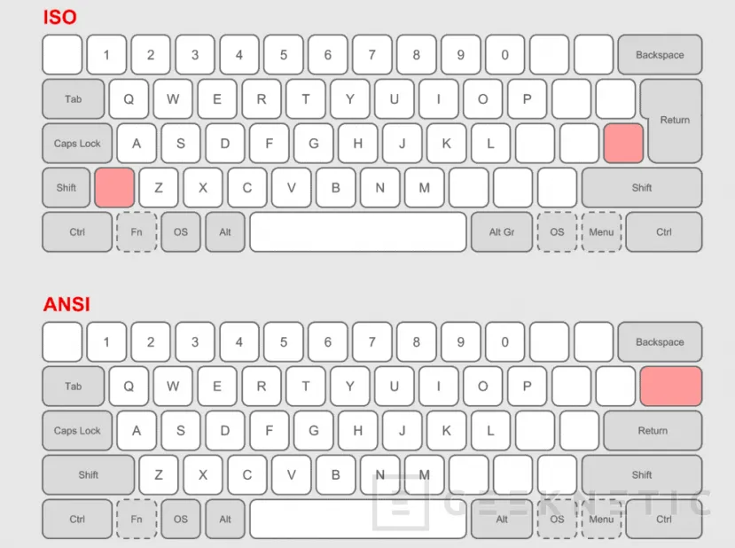
Q) What is a layout?
A) This image will help you to understand the difference between an ISO and an ANSI layout
| Quantity | content |
|---|---|
| x | 3D printed files |
| x1 | rp2040 WeAct Studio |
| x84 | 84 keycaps (ISO/ANSI) |
| x84 | Mx style switches |
| set | Costar stabilizers |
| x84 | 1N14148 diodes |
| x1 | Usb-c male connector |
| x1 | Usb-c female connector |
| x4 | 33x5x1.5mm silicone feet |
| x1 | 10 meter 22 AWG flexible cable |
| x23 (minimum) | M2X14mm screws |
| x19 | M2X4mm screws |
Tools needed:
- soldering iron
- hot glue
- scissors
- needle (or something pointy)
There are 4 variables of plates but only the 3d printed PCB works with the default ISO layout. This also applies for the main.py configuration but it can be edited easily
If you are not into handwiring and have some free time you can check this pcb generator here
The model of the raspberry has to be from WeAct Studio. If not, search the firmware of your raspberry here.
First download CircuitPython.
After that, Get the raspberry in boot mode:
Hold down the boot buttom and plug the raspberry into the computer.

Now, the computer should detect a new external storage.
Drag the downloaded UF2 file to the Pico. The storage will reset and appear with the name CIRCUITPY.
Now we have to install the KMK firmware.
Grab the latest version of KMK and extract all the files from the zip.
Copy the kmk folder and the boot.py to the raspberry.
Download and copy the main.py to the raspberry.
You're done!
This is the most tedious part of the build, it will take you some time to finish it.
You will need this diode bending cube:
this is the 3d printed pcb:

We will start at the back of the board with the columns of the matrix.

For better cable management mark the position where the raspberry board will be. This will help you to know the length of the cables.
Be careful with the holes of the screws! Do NOT glue the board into the pcb (yet)

This is is the diagram of the weact studio rp2040, the GPX pins will be used for the matrix of the keyboard.
The order of the pins can be specified in the main.py which means that you can solder the cables wherever you want as long as you modify the file.
Note: GND are not GPIO pins, do not use them.

Put the cables in the columns and cut them with the enough length to join their respective pin.
If the cables won't fit in the columns you can use silver wire as long as you secure the conection between the wire and the diode.
If you didn't understand this don't worry, it is the next step
Here is my setup:

Here comes the worst part of the build, you have been warmed.
The best way to show how the diodes are conected to the columns is with these pictures
pointy thing and diode bending cube are needed here
the diode pins will be here


The connection between the column and the pin is formed by going through the cable.
Here is where the pointy thing comes in handy.
Check where the hole of the column is and prick the cable.
The tinier the hole the less will fail the conexion


Do the same with all the columns.
You will need to do this at least 84 times


Note: check the Diode orientation


with all the diodes mounted to the columns you can now hot glue the raspberry to the pcb (make sure to put a layer of hot glue on the pcb
before)
You can also add some hot glue to the cables
The rows just need to solder the cables to their respective pin and good cable management.
Note: The ISO enter is connected in the third row
You will need a usb c male to female cable. You can buy usb-c connectors and solder the cables or buy one.
Your printed PCB should look like this:


This was the first prototype of the pcb
now you can connect the pcb to the PC and check if all the keys work as it should with a keyboard tester and something to bridge the connections of the matrix
Check if all the keys are working before mounting the case
glue the usb adapter to the hole case (usb-c hole) place the pcb to the case, be careful not to pinch the wires.
now you can use the M2x4mm screws to secure the pcb to the case.


For the stabilizers you will need at least one for the spacebar in order to make it work properly

The stabilizers need to be installed in a specific orientation

You can put the rest of the costar pieces later. If you don't know how to install the stabilizers this video may help you
take the plate and the case and put it upside-down. make sure the case and the plate is alined and start putting in the screws
There should be the less gap possible between the plate and the case

You can now put the silicone feet.
The switches are installed in a specific orientation.
It is recommended to check if the switch works before mounting the next one. This part is where the switch tends to fail as the upper pin needs to go through the row cable

You can now mount the costar stabilizers and the keycaps.
Congratulations! You can now enjoy your new finished keyboard and tweak it however you like.
- Thanks to 50an6xy06r6n and stingray127 for the inspiration of the PCB.