Need to control your laminator's temperature precisely because you use it for performing temperature-specific things like applying photosensitive dry film to PCBs or trying out the toner transfer method? This lets you do that.
- AmazonBasics Thermal Laminator; ~$21 as of this writing.
- 120VAC to 5VDC transformer; ~$5
- MAX6675 and K-Type thermocouple; ~$5 -- you'll need to remove the chip and mounting pins from the little PCB for attaching to the final board.
- ATMega328pb microcontroller; ~$2 -- an ATMega328p would probably work just as well, but you may need to double-check the pinouts.
- Common-cathode 4-digit 7-segment (+decimal point) Display; ~$1
- AS1108WL common-cathode LED array controller or equivalent; ~$4
- PEC11S Rotary encoder w/ button; ~$3
- CH340G USB-Serial UART adapter; ~$1 -- not strictly necessary if you're comfortable programming the chip via the SPI bus
- CLX6A 3.5mm x 3.5mm RGB LED; <$1
- A relay (for turning the heating element on/off)
- A variety of passives, a diode, a logic-level p-channel mosfet, a logic-level n-channel mosfet (all SOT-23), etc; see the schematic for details.
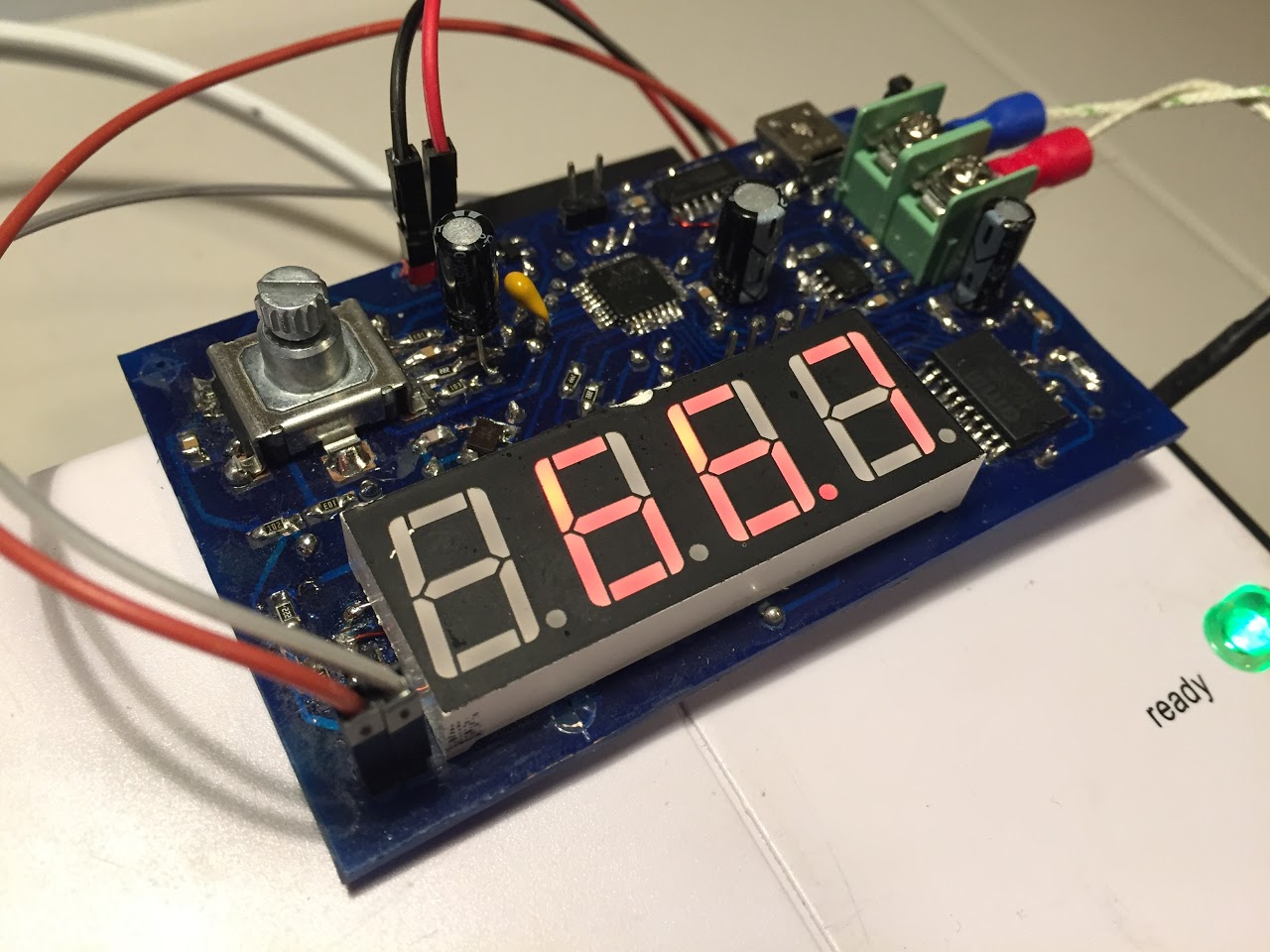
Just turn the rotary encoder to set the target temperature; when you've found your target temperature, press the rotary in to activate its button. That's all.
There's a single RGB LED on-board; various LED colors mean various things including:
- Off: The heating element is off.
- Blue: The unit is starting up.
- White: You are setting the temperature right now.
- Red: The heating element is on.

The included schematics and layout are both correct (as far as I know), but if you observe the photos linked here, you'll see that they differ in slight ways. If you look carefully, you'll see that I've had to correct several oversights by using bodge wires or, in two cases, installing capacitors that I neglected to include in the original design. The attached schematic has, though, been corrected to account for these oversights.
In case you're curious about the errors I made, they were the following:
- Added the bypass capacitors to the wrong pins of the microcontroller. I did not notice this problem until very late in the game when I was trying to diagnose what was causing some erratic behavior. The root cause of this was that I did not pay close-enough attention to which pin was the ADC's VCC and which pin was the microcontroller's normal VCC. Really, though, there should be bypass capacitors for both, so I've updated the design to include them for both VCCs.
- Neglected to connect the CH340G's GND pin to anything at all.
- Mis-connected the N-Channel mosfet used for switching the laminator's relay. I misread the datasheet and had swapped the source and drain pins.
- A couple traces were just a little too close together and had to be cut apart during various fabrication steps.
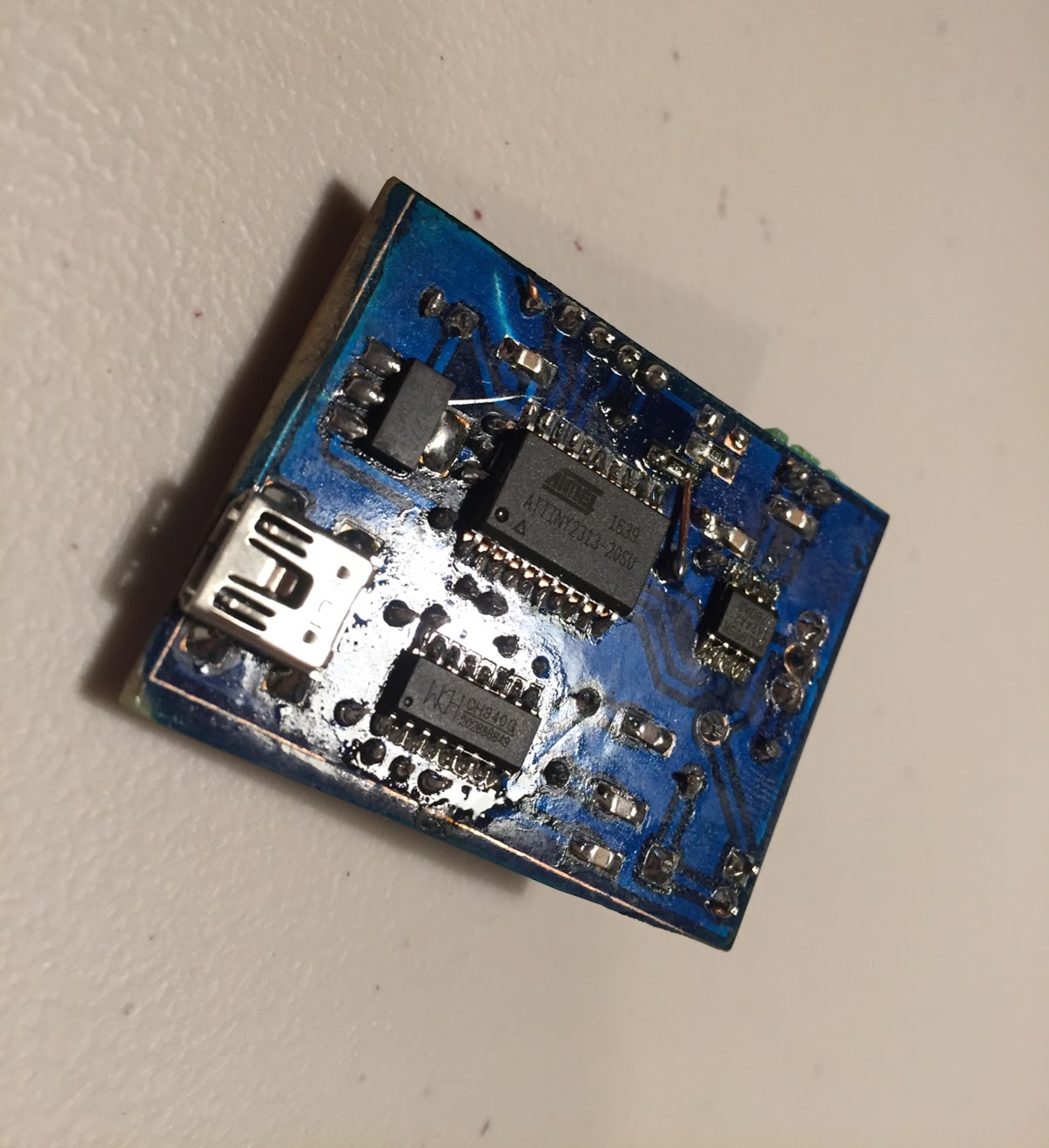
The first version of nespole was intended to be just a bit simpler; it would fetch measurements from a thermocouple in a way very similar to what Nespole 2.0 does (except via a slightly-newer MAX31855). I encountered a ton of trouble getting the thermocouple chip to return reasonable data, and eventually gave up and reprogrammed this board to just provide a USB interface for flipping the relay on-and-off.
There are a couple things I'd perhaps change in a later iteration:
- Spend more time tweaking the layout so I can get the relay control header near the top of the board instead of the bottom. This is something that could probably be done without a huge amount of further effort, but sometimes it's important to settle for "good enough".
- Place the alignment points off of the final board area instead of within it. When making this board, I was using copper clad that was only very slightly larger than the final size and decided to be a little conservative.
- In the end, I used 5566 bytes of flash and only 300 bytes of memory; I could probably get by with a lower-powered microcontroller. It's a little hard to beat the price of the ATMega328pb, though, so that might be more of a challenge than it is actually worth.