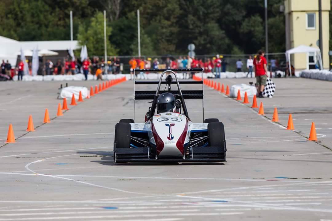
Vehicle Model is based on the vehicle of Road Arrow Formula Student Team from University of Belgrade, Serbia
Upcoming years will bring radical changes to how we view commuting and traveling. Electric cars and self-driving vehicles are stepping in. In order to keep up with the future in the fast lane, we have to put ourselves in a position of the engineer of the future and be part of that inevitable change. This does not mean to only rehash existing ideas, but also build on them and improve them ourselves. This article is about my work and approach to the solution of one of the major parts of any type of a vehicle so far – TORQUE VECTORING development. My solution was designed for a 4 wheel electric (sport) car.
During my time as a Formula Student member of Formula Student Road Arrow Team University of Belgrade, I had a great time with developing electronics for a combustion car. During that time, we came up with the project of an electric vehicle for the same competition. My goal was to develop a base for a Torque Vectoring algorithm. Most algorithms that I have read are based on real time data sensoring without pre-model. Since our team hadn’t had a sufficient amount of funding to start building a car right away, I started making a physical-mathematical model of the car's behavior. This was my final thesis for my BSc. A model of sport vehicle handling with 4 wheel electric drivetrain. All simulations and implementations have been conducted using Matlab.
All vehicles modeling starts with a bicycle model. This is very good if we consider a car traveling at a low speed, or to be more precise, taking corners at a low speed. But, in the motosport world, we drive totally opposite – finding a perfect racing line, late braking, starting acceleration from apex etc. Therefore, the car reaches its boundaries. So, I started my model with 2 parallel bicycles which are hard connected. One is for the left side of the car and the second is for the right. I have introduced this approach since it will include weight (mass) transfer and a slip angle. So, the center of the corner will not be aligned with the rear axle, but somewhere towards the middle. Since, outer wheels have more grip during cornering due to higher weight caused by weight transfer and lateral forces, they dictate car handling during cornering. That is the reason for having two bicycle models.
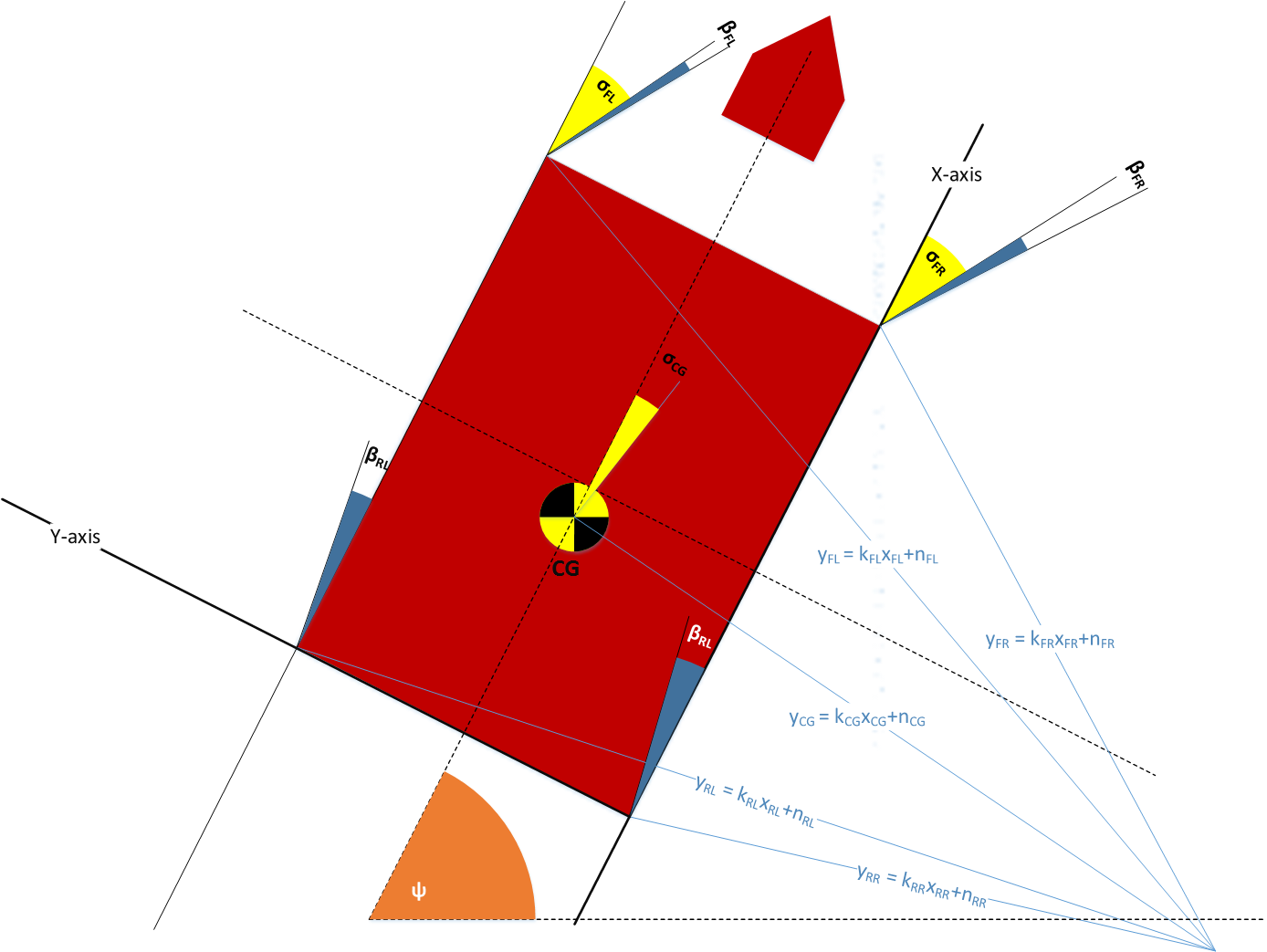
As seen on the previous picture, the car is driving to the right so the front left wheel, or more precisely the front left tire’s grip and slip, will dictate cornering and the car’s handling. Due to this fact, all calculations will be calculated according to this side of the car, and the right side wheels’ behavior is derived from these calculations. Same applies vice verse for the left hand corner. Parameters are explained as follows:
Parameters: R - diameter of the curve L - base length δ - steering angle Ψ - yaw β - slip angle α - difference in angles δ(t)- β(t) (xcm, ycm) - coordinates of the vehicles center of mass
As it is known, tires' contact patch is the only part that interacts with the ground and makes a car go forward (or sideways). Well, this happens when the tire exceeds its lateral force grip and starts to slide. Best racing drivers are able to feel when the car is at its (tire’s) limit and they drive at the maximum slip angle during cornering, moving the pivot point (center of the curve) towards the middle. Unfortunately, tires’ slip angle can be only approximately calculated during racing, but tires factories provide test results of their tires’ slip angle.
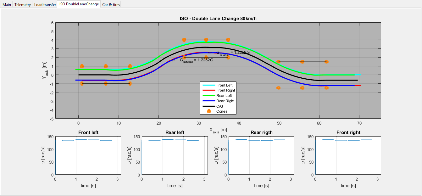
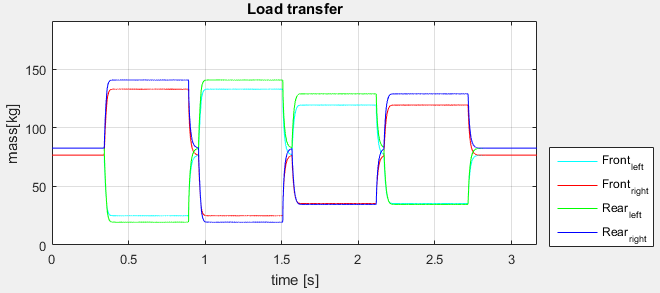
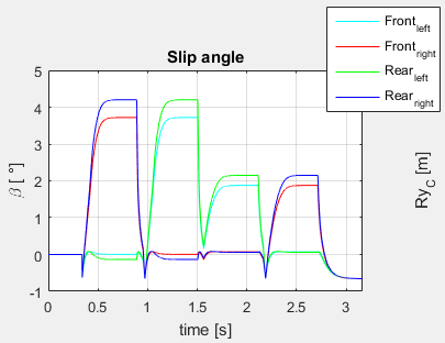
Implementing slip angle and weight transfer influence inside of my algorithm, the results are shown in the following picture:
Wish you a nice racing weekend, good luck!