
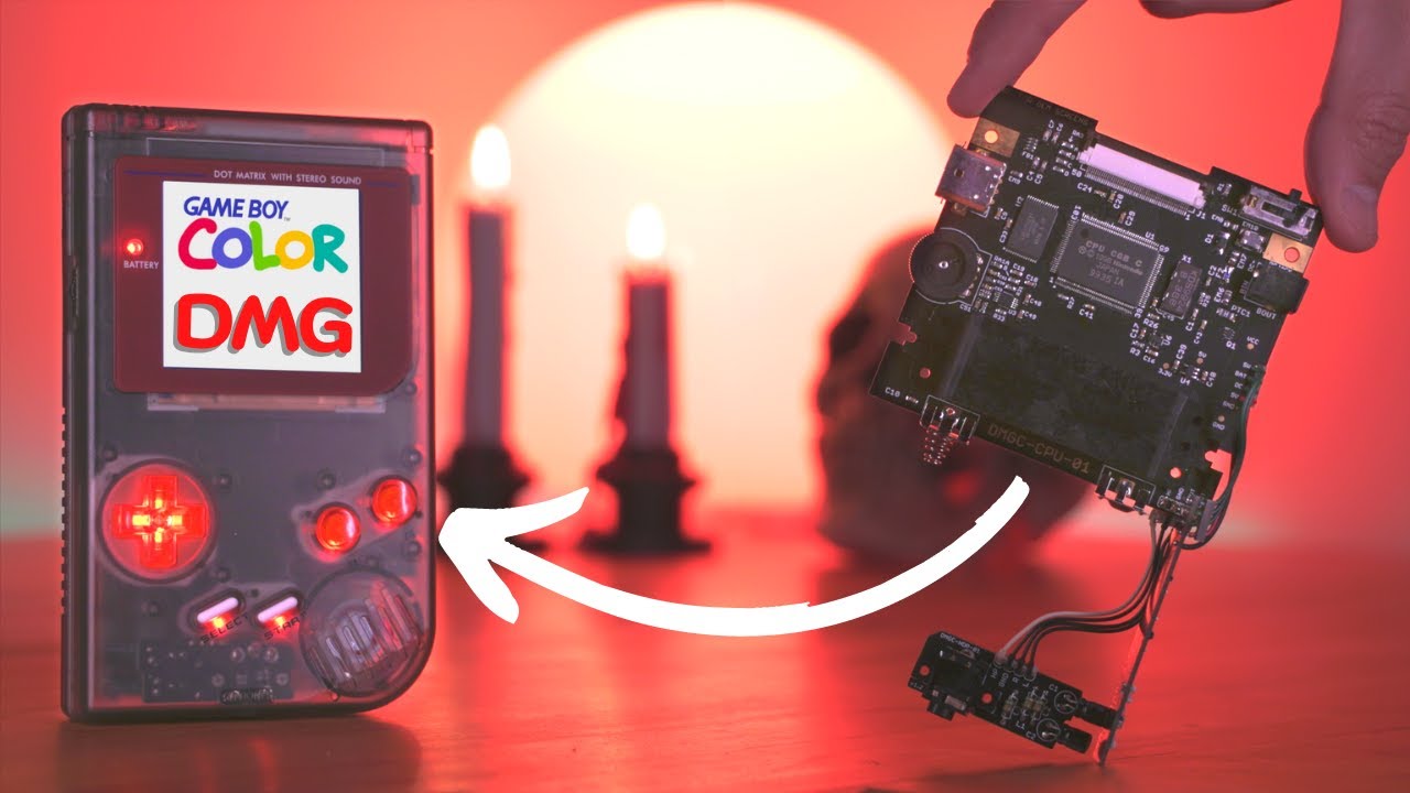
This is my design for an original Game Boy (model name DMG) with native Game Boy Color support, and a handful of improved features! This is an original creation - newly designed PCBs, with only some necessary components harvested from an original Game Boy and Game Boy Color (no hardware emulation – this project uses the original CPU). Here are the project goals:
- An original Game Boy aesthetic, using the original Game Boy shell and interface (link port, volume wheel, power switch, etc.), but with the capability of playing both Game Boy and Game Boy Color games.
- A nice, large IPS screen – the GBC Q5 XL IPS Backlight with OSD kit – with brightness and color palette control via the "navigation switch" housed where the contrast wheel used to be. (I will refer to the PCB attached to the Q5 screen as the “Q5 board”)
- A modernized, efficient switch mode power supply that can run off 4x AA batteries or input from the DC jack, just like the original DMG. Testing shows that playing with NiMH AA batteries can yield more than 18 hours of gameplay at normal settings (AKA, the way I normally play it - maximum brightness and headphones).
- Louder, warmer sound through a modern audio amplifier.
- The option for tactile switches for the face buttons - like the GBA SP.
- The option for backlit buttons, with multiple color modes and brightness control.
- No externally viewable case modifications, outside of trimming the DMG power switch cover for Game Boy Color game compatibility.
The code name for this project is DMGC. This console uses four PCBs, just as the original DMG model did - a CPU board (DMGC-CPU), display board (DMGC-IPS), power board (DMGC-PWR), and headphone board (DMGC-HDP). All circuit board assemblies have their own separate folders in this repository which contain detailed descriptions of operation, source files for schematics and board layouts (designed using Eagle), exported Gerber files, and some other relevant files.
Do you want to make one? Then you NEED TO READ this entire page. Seriously. All your questions will be answered.
Before I go any further, please read this VERY important disclaimer, if you are thinking about making this yourself. Don't let this picture happen to you!

I made this project first and foremost for my own purposes. Nearly all of the features I have included are things I personally wanted. I have tried my hardest to make the project modular, if others would like to improve or change things easily, and I have also tried very hard to make the design somewhat less prone to potential errors during assembly (such as spacing out power pins on the FFC connectors). But in the end, every decision I made was for what I wanted the final product to be, with my skill level in mind.
Schematics, gerbers, and the BOM are provided in the various folders. If you choose to build this project yourself, be warned - this is a considerably advanced, and expensive build. You must be comfortable with the fact that you may lose or damage expensive components. You are 100% liable for any damage done to your property or yourself. I am not responsible for any damage or loss of property incurred while attempting this project, or after completion of the project - you alone accept all risk. While I am confident in this design, I cannot claim full compatibility with every system configuration. And there may be latent issues that have yet to crop up. I will update this repo if I encounter any, and if you see anything I may have missed, or some dubious design choice, feel free to ask questions or comment as such. Corrections are welcome. However, I will not obligate myself to providing tech support. You accept all risks and costs associated to this build if you choose to attempt it.

DO NOT attempt this project if you are uncomfortable or inexperienced with detailed electronics troubleshooting, or are not proficient in soldering! You will AT MINIMUM need to be proficient in drag soldering and hot air reflowing. If you have not gained proficiency in these soldering skills, DO NOT ATTEMPT THIS PROJECT.
If you attempt the build, start with trying to assemble DMGC-PWR-01. This is the toughest board to assemble, and it requires no donor components.
There are a handful of categories for the parts you need for this build. Please review all of them! The total BOM cost will come out to anywhere between $200 and $250 (NOT including the cost of a donor Game Boy Color console!) depending on the options you choose, which OEM parts you re-use, and any potential deals you can get on certain parts. Note that with the exception of a few components from a donor Game Boy Color, most of the electronic parts are brand new.
First and foremost, the circuit boards. I have created these four boards myself, and you will need all of them:
- DMGC-CPU-01: The CPU board, where the brains are held
- DMGC-IPS-01: The front display board
- DMGC-PWR-01: The power supply board
- DMGC-HDP-01: The board that holds the headphone jack
I have provided the zipped Gerbers and ordering details in each of the board folders above, as well as shared projects on PCBWay. For full disclosure, if you buy the PCBs from PCBWay, I will receive 10% of the total sale towards buying more boards from PCBWay. You can alternatively use these Gerbers at other PCB fabricators if you would like.

I also sell them on my Etsy store, so you don't have to buy multiples! (Click the banner!)

The DMGC uses mostly all-new parts. This isn't a direct-transfer style project! The master BOM with every electronic component required for the four circuit boards are provided in this root folder in Excel format. Furthermore, each folder for each board will contain their section of the BOM near the bottom of each README that contain all of the electronic components needed for that specific circuit board. Note that some parts may be out of stock at the links provided, but many can be found at alternate other retailers online, or have a proper substitute. Here is a saved cart from Mouser that contains all the parts in the BOM Excel, including some duplicates. Double check to see if any parts are missing, and consider ordering multiples of some parts. There also may be some parts you want to remove (like the tactile switches).
If a part is backordered, or out of stock - check the Excel file, or the BOMs listed at the bottom of each board's folder in this repo. There may be alternate part options. You can also check for stock at places like Digikey. And you can always use Octopart.com to help find in-stock parts at other websites. I can't maintain the cart for every out-of-stock part, so please do some research :)
This project requires at the very least a donor DMG console and a donor GBC console.
There are a handful of parts that I have not located aftermarket substitutes for, and will therefore necessitate an original Game Boy console to salvage from. Please note that removing these parts is not a trivial task, and requires advanced soldering and desoldering skills to be successful.
The following parts are required from an original Game Boy Color console:
- U1 – CGB CPU (all revisions except REV E, which is incompatible)
- X1 – 8.388 MHz crystal oscillator
The following parts can be salvaged from a Game Boy Color, but aftermarket options exist:
- U2 – LH52256CVTXIZ (SRAM); alternate: https://mou.sr/3f8G0Mi
- EM10 – input filter; alternate: https://mou.sr/3FiMvXw
The following parts are required from an original Game Boy (DMG) console:
- SW1 - Power switch
- DC jack
- Headphone jack
The following part is required from an original Game Boy (DMG), or a Game Boy Four Player Adapter:
- EXT port
The following parts can be salvaged from an original Game Boy (DMG), but aftermarket options exist:
- VR1 – Volume dial
- P1 – Cartridge connector
The following is the high-level BOM - basically, the Game Boy part. Note that parts that deviate from the ones listed here (like different shell designs) might necessitate different fitment modifications, or end up being incompatible. Note that this list is not a comprehensive list of all the places you can get these parts. I encourage you to search around if you can't find what you want here.
- Shell: I generally recommend the Funnyplaying "IPS Ready" ones if you don't want to trim anything, but the color and style options are limited. If you don't use these, then you're on your own for how to prepare it - generally, you can follow guides for preparing a Pocket for an IPS screen kit.
- RGRS: Game Boy DMG Shell – Factory A [Note: this one requires trimming!]
- Funnyplaying: DMG IPS Q5 Custom Housing
- Screen Kit: This is the important one. You need this specific type of kit - the Q5 IPS with OSD. It goes by many names, the maker is Hispeedido (not FunnyPlaying). Kits that have the screen laminated to a GBC lens are not compatible, but kits that include a lit-up logo on the bottom part of the screen are fine to use. Make sure you DO NOT get any Game Boy DMG versions - they are not compatible! Also, be sure to test this screen kit before installing it, preferrably with an original Game Boy Color. Sometimes they arrive damaged, and once you've installed, it may not be possible to get a refund.
- Screen Centering Bracket: You can find the design file for this bracket in the DMGC-IPS-01 folder. It's a custom designed bracket I made that is required for holding the screen in place. You will need access to a 3D printer for this part, or you can order it online from 3D printing services by uploading the file.
- Lens: You must get the "IPS" style of lens, as the viewing area is larger.
- RGRS: FunnyPlaying DMG Q5 IPS Lens
- FunnyPlaying: DMG RetroPixel IPS Glass Lens
- Buttons: Funnyplaying models are generally OEM-like (IMO), but you can also use OEM ones. For the above build, I used Kitsch-Bent silicone buttons. Bonus: NES controller buttons fit inside the DMG.
- Kitsch-Bent: Clear Silicone DMG Buttons
- RGRS: DMG Buttons
- LabFifteen: Game Boy DMG Buttons
- FunnyPlaying: DMG Custom Buttons
- Membranes: Important, but very forgettable! You will need them even if you install tactile switches. You will, however, not need them if you use the Kitsch-Bent buttons.
- Speaker: There are tons of options for this as well, including using the OEM one.
- RGRS: FunnyPlaying Clear Game Boy DMG Original Speaker
- FunnyPlaying: Clear DMG Speaker
- Battery Tabs: This one is another part I commonly forget about. You can use a salvaged set of tabs, or order new ones.
- Stickers: Completely optional, but they can really bring a build together. Especially if you have custom DMG Color stickers!
- Nextstopplease: DMGC Labels
Buying from RGRS? Consider helping out some cool people with these referral links:
Or use one of these discount codes at checkout:
- Nataliethenerd
- B23N
- Tito
Note that the IPS kit I have listed is the easiest IPS kit to use that is compatible with this build. It includes an image centering feature, so you don't need to fiddle with centering it manually in the shell. Other kits likely would not center nicely in the DMG shell! This kit works electrically, but requires you to center the image yourself. If you end up making some sort of 3D-printed bracket to support this screen, feel free to share it here.
You can check out Tito's video on the DMGC to get an idea of how the assembly process generally goes.
Here are some pictures of the assembly process after testing the functionality of all the boards separately. Detailed images of the circuit boards alone are shown in their respective folders. These pictures are of a previous revision, v1.2, but the process remains the same. You may notice some minor cosmetic differences in these pictures from the current revision boards.
I highly recommend reading the information in the Troubleshooting and Testing folder above. In it, I detail the testing procedure that I follow before fully assembling a DMGC. It is far easier to do this than to have to disassemble things when something doesn't work.
First, I started with the back half of the DMG shell. The PWR board needs five ~2.25" wires that wrap around the screw post on the side of the shell. In addition to the PWR board connections, the HDP board needs four ~2.6" wires. Also, the flat flex cable (FFC) should be inserted into the CPU board first, because the connector will be inaccessible after screwing the CPU board in the shell. After I soldered all the wires between the three boards and secured the FFC, I placed the assembly in the shell, and secured it with the proper screws. I put a game in the cartridge slot to keep the CPU board in place easier while assembling.

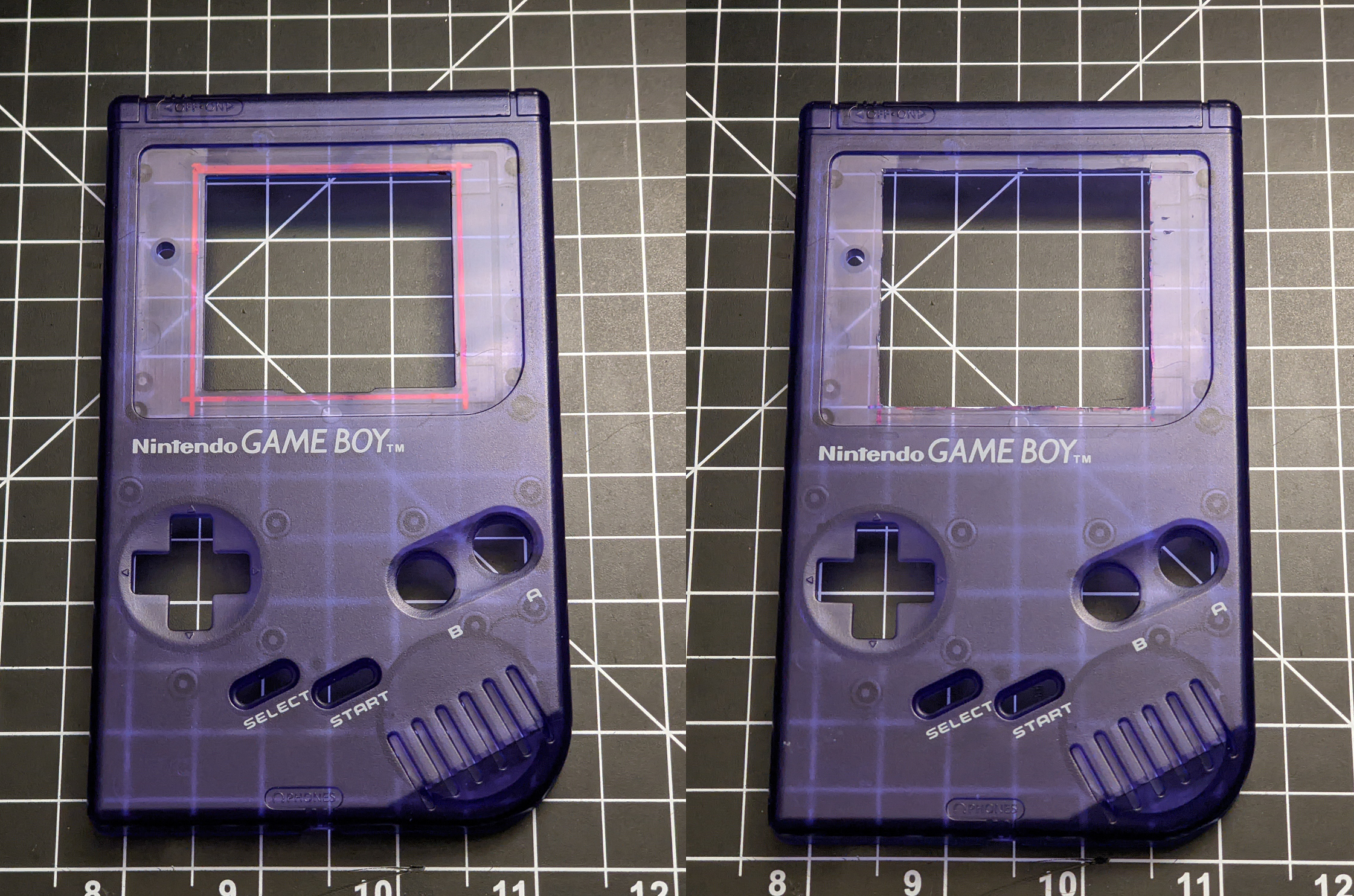
Before placing the power switch cover in, I cut a notch in it so that it wouldn't prevent Game Boy Color games from being played in the system. In the left picture below I’m using Game Boy games, and in the right picture I'm using Game Boy Color. And you can see that the power switch is blocked from turning on by the GBC cartridge for the original model.

After the back half was done, I prepared the Q5 board solder pads. I cut six 30 gauge wire segments and soldered them on the brightness, palette, battery, and OSD input pads. These will be soldered to the rear of the IPS board after installed. You don't need to include a wire to the GND pad.

For the top half of the shell, as per instructions on a similar DMG IPS kit that uses the Q5 screen, I very carefully cut ~1 mm of plastic around the border of the viewing port, and trimmed any extra plastic to make the surface underneath the lens smooth (there are "IPS ready" shells that should not require this cut). I used a black paint marker to color in the edges of the newly cut plastic, so they would not be visible at an angle. And I trimmed two posts off of the shell so the screen would fit flush against it.
Then I installed the front lens, and placed the screen, backed with the 3D printed bracket, into the front half of the shell. I made sure to clean up any stray fingerprints or dust while assembling this part. Once the bracket was placed and flush with the shell, I put the buttons in and placed the IPS board over top, slid the Q5 screen FFC into the connector on the PCB (making sure it fit without any added stress on any connections), and secured it all in place. Then I very carefully soldered the wires from the Q5 board onto the appropriate pads on the IPS board - making sure not to melt any plastic on the shell.

**Note: Be extremely careful with the screen. It is fragile. If you break it, you can sometimes buy one separately.
If you installed the 7-pin headers for programming the ATTINY easier, you might want to tape off the headers with kapton tape. If everything is installed correctly, these shouldn't interfere with anything on the CPU board after the halves are screwed together (C47 is the closest component), but you may want to consider it anyway.

After that, it was just a matter of connecting the FFC from the CPU to the IPS board, tucking it under the boards ensuring no kinks or sharp bends, and screwing it together. Once assembled, I opened the OSD menu for the IPS kit (Select + A + B) and changed the vertical and horizontal offsets (my values were 78 and 29, respectively) to center the image on the screen. The image centering function is one of the biggest reasons I chose this IPS kit.
I suggest running the color tests in the 240p test suite ROM, if you have a flash cart to run it on. It will tell you if you have any poor connections on the FFC lines - the screen might work, but you might be missing a connection on one of the 15 RGB pins! If your colors look off, reflow the connections on the top row of pins on the CPU and/or the FFC connectors (the issue may be on the CPU board, or the IPS board). This picture (provided by JackV) shows a before and after pic for reflowing a few mis-soldered color pins.

Next to an original DMG… one can really see the improvements!

- Select + A + B: Open the OSD menu
- Select + A: Enter
- Select + B: Exit
- A: Increase
- B: Decrease
- Rock up: Advance screen brightness setting
- Rock up/Hold: Toggle on-screen battery indicator
- Rock down: Advance screen color pallete setting
- Rock down/Hold: Toggle on-screen pixel grid
- Push in: Toggle button LED color setting
- Push in/Hold + D-pad Left: Decrease button LED brightness
- Push in/Hold + D-Pad Right: Increase button LED brightness
- Push in/Hold when turning on power switch: Disable LEDs until another power cycle
For these estimates, battery life is calculated using four eneloop pro NiMH AA batteries (total of ~11800 mWh). Keep in mind that these are very rough estimates. I tried to be conservative in the power draw measurements, so hopefully these numbers represent a mostly worst case. Actual playtime will vary due to a variety of factors - changes in efficiency and performance as the battery voltage changes, differences in game audio, etc.
I measured the power draws using a MiniWare MDP-XP Mini Digital Power Supply, and estimated the average power draw shown on the display (I tried to bias towards a higher value). Input voltage was set to 4.4 V, just above the point where the power LED dims. I tested with the Legend of Zelda: Link's Awakening, letting the game sit on the title screen after the intro cinematic, where sound is relatively loud and the screen is mostly white. The audio gain on the test console is set to ~0.38 (see CPU board for more detail on this gain value - a higher gain can greatly impact power draw at high volumes out of the speaker).
| Test Criteria | Power Draw | Estimated Battery Life |
|---|---|---|
| IPS max brightness, NeoPixel LEDs max brightness (white), speaker volume 100%, Everdrive X5 | 1150 mW | 10.3 hr |
| IPS max brightness, NeoPixel LEDs off, speaker volume 100%, Everdrive X5 | 900 mW | 13.1 hr |
| IPS max brightness, NeoPixel LEDs off, speaker volume 100%, original cartridge | 750 mW | 15.7 hr |
| IPS max brightness, NeoPixel LEDs off, headphones, Everdrive X5 | 725 mW | 16.3 hr |
| IPS max brightness, NeoPixel LEDs off, headphones, original cartridge | 650 mW | 18.2 hr |
| IPS min brightness, NeoPixel LEDs off, headphones, original cartridge | 475 mW | 24.8 hr |
Note: If powering through the DC jack instead of batteries, an OEM adapter may not be able to supply enough power to the DMGC at maximum settings. Furthermore, cables like these will require at least ~200 mA output from the USB port for reliable operation at all settings. (USB 1.0 and 2.0 are likely not sufficient for higher loads, such as with the button LEDs on)
I mentioned the sound of the DMGC is "warmer" than an original GBC - it's bassier with less buzzing background noise (owing mostly to the modernized power supply). I connected the headphone jack to my computer's microphone input, and used Audacity to obtain line out recordings. Then I graphed the spectrum using Audacity's "plot spectrum" analysis tool. You can see the larger gain at the lower frequencies in the spectrum plot of the DMGC. I also took some recordings of the pro-sound output as well - it's even cleaner than from the amplifier. I'm not an audiophile, but I'm pretty sure the DMGC all-around sounds nicer, at least through headphones. Listen for yourself! (GitHub only allows for video files to be embedded, MP3 files are provided above)
audio_GBC.mp4
audio_DMGC.mp4
audio_DMGC_pro.mp4


Want to improve this project? Maybe try one of these things (because I probably won’t):
- This console uses 4x AAs instead of a single rechargeable battery in order to maintain the feel and weight of the original DMG model, but an obvious change to the build is to utilize a LiPo battery with proper battery management. The DC jack could be repurposed to charge the battery instead. With the advent of affordable rechargeable AAs, the appeal of the AC adapter is diminished, so this would be a good repurposing. However, the maximum output current of most DMG AC adapters is rated for ~200mA at ~6V, so charging would be considerably slower than, say, fast USB-C charging.
- Restoring the IR functionality of the GBC could also be done, as there is ample space for it on the circuit board and shell - I just do not trust myself with forming plastic to look nice, and it wasn't at all an important part of the build for me.
- Finding aftermarket equivalents for all the different required DMG parts would be ideal, instead of using a (hopefully broken) DMG for a donor console. For my personal build, I used original DMG components because I had a damaged console lying around, but you can easily find DMG-style volume wheels and cartridge connectors online. The tricky parts are as follows:
- A GBC EXT port can be used in place of the DMG one (but would look kind of weird in the DMG EXT hole in the shell).
- There are a few power switches I've ordered to try out in place of the DMG one, but I haven't gotten around to testing them yet. There's no one fully drop-in replacement that I've found, though, so it would require circuit modifications.
- I haven't been able to locate a headphone jack exactly the same as the DMG one, but the circuit could be adapted to accept a different style.
- The DC jack could be tricky. I haven't looked very hard for any kind of replacement for this.
- Any other of the various popular GBC mods could be incorporated if desired - bluetooth, overclocking, etc. With the ATTINY on the IPS board, one could incorporate button combinations to interface with these mods without the need of any additional buttons or (shudder) touch controls.
- I thought about adding LEDs to the back of the front PCB, so that light would emit out the edges of the console with a translucent or transparent shell, but I never got around to trying it out.
- When the button LEDs are on max brightness, using the NeoPixel LEDs specifically (especially on the white color setting), a ~1 kHz whine can be heard through the speakers or headphones. I attempted to remove this whine with different methods – adding filtering to the supplies, using separate supplies for the audio/LEDs, etc. – this lowered the noise amplitude, but I wasn’t able to remove it completely. And obviously adding a filter on the audio output is a no-go since 1 kHz is smack dab in the middle of the audible range. Changing to different color settings can reduce the volume of the whine, red in particular seems to be quite low, and setting the LEDs at lower brightness levels (or just completely off) removes it. So just don’t play with the LEDs on really bright if it bugs you! I kept the color sweep during power-on enabled on every color setting - if you want to disable the LEDs for the entire play session, hold the navigation dial in when you turn it on (but at that point... why did you bother adding the LEDs in the first place?)
- The original DMG A/C adapter that plugs into the DC jack cannot support play with maximum settings (backlit buttons, maximum brightness, maximum speaker volume, flash cart). If you start up the Game Boy with less than maximum settings, then during gameplay increase the load on the power supply such as by increasing the screen brightness or maxing out the volume on the speakers, the console may shut off. If you're powering the console through the DC jack, I suggest using a USB adapter cable into a USB 3.0 port (or some style of USB wall charger)
I'll update this section as more people begin to build these.
Q: How do I lower the brightness of the power LED? I can't see anymore.
A: You can pick a different LED model with lower brightness, or you can simply increase the resistance of R1 on the IPS board. Higher resistance = lower brightness. I would try 10 kΩ first if 5.6 kΩ is too bright. (If you want to dim the low power level LED brightness, increase R2 resistance as well!)
Q: My EM10 has an extra leg in-between two of the other ones. Can I use this part?
A: Yes, just bend up the extra pin so that it doesn't contact any of the nearby pads. It is an unused anchor pin.
Q: Why does the audio sound like [not normal]? (Usually asked while testing during the middle of a build)
A: The audio will sound terrible if you do not have your IPS kit connected. You can use the CPU board's FFC connnector for the IPS kit if you would like to test it without the IPS board in the middle. Furthermore, the speaker will be muted if you do not install the headphone board.
Q: Sometimes the power switch is finnicky and the system won't power on consistently. Sometimes the IPS screen will turn on, but only the backlight, not the actual image. What gives?
A: Clean your power switch (without batteries inserted or power applied) by dripping isopropyl alcohol inside and flipping it off and on a few times. This will hopefully clear up debris or oxidation. Opening up a DMG power switch isn't the funnest thing to do. I have found that if the IPS kits receive intermittent power while turning on, it will lock out their image processing until you power cycle. It's not damaging, just annoying.
Q: When I have the front and back halves of the DMGC separate, everything powers on correctly. But when I screw the two halves together, it doesn't turn on. Why?
A: Check to make sure the wires connecting the CPU and PWR boards do not have long stubs of wire sticking up out of the CPU board. The IPS board's navigation dial has metal housing that can short these wire stubs together if they are too long. Trim them short so they don't touch the metal shielding.
Q: Sometimes when I'm using batteries and turn the power switch on, nothing happens.
-AND/OR-
Q: Sometimes when I play my DMGC, and I set it on the table too hard, the game resets. Why?
A: Usually this is because you're using NiMH AA batteries, like eneloop pros. These batteries have slightly shallower positive tabs than regular alkaline AA batteries. This makes contact from the batteries to the tabs not as robust as regular AA batteries. Unfortunately this is a problem on ALL DMG consoles, not specifically the DMGC. This could be due to a poor connection on any one of the four batteries inside the bay. You can swap out battery contacts that stick out a bit farther that make better contact with the batteries, or you can try reseating or literally spinning the batteries in the battery bay to make better contact. (Or, you could always use regular AA batteries or an A/C adapter!)
Q: Can I use this with a DMG CPU?
A: No, this is only for use with Game Boy Color CPUs. There are some other projects around that recreate the DMG, like this one.
Q: I really like this project, but I just wish it was in a smaller, more cramped shell, with way worse battery life. Can you help?
- The board outlines and many of the footprints for the DMG components from this DMG recreation project were used for reference on the original revision of the project, so very special thanks to Rolf, bit9, and nitro2k01!
- Thank you to gekkio for their Game Boy repository and github: I referenced many of the DMG and GBC resources during this build, even just for looking at pictures of different PCBs.
- Immense thanks to the users of the r/Gameboy and gbdev discord servers for technical resources, troubleshooting/feedback, and suggestions. Could not have done this without your support. Shout out to kevtris for design feedback and lidnariq for troubleshooting support!
- Thank you to Tito, aka Macho Nacho, for his amazing video covering the project.
- Of course, huge thank you to everyone who has donated and supported me, and to those who have built their own DMGC! I love seeing pictures of builds, so feel free to share them with me on Twitter, discord, or via email!
This work is licensed under a Creative Commons Attribution-ShareAlike 4.0 International License. You are able to copy and redistribute the material in any medium or format, as well as remix, transform, or build upon the material for any purpose (even commercial) - but you must give appropriate credit, provide a link to the license, and indicate if any changes were made.

This project is the culmination of nearly a full year of research, development, and testing. I have made this project completely open-source, and have put hundreds, if not thousands of hours of work into it, so that many people can enjoy it. Please give me appropriate credit where credit is due.
©MouseBiteLabs 2022