GUIDE on how to connect up a MAX31865 and PT100 sensor to SKR V1.4 board
- You CAN NOT mix PT100/PT1000 and thermocouples:
If you have only one hotend then you can have the following:
- Thermistor (that is an ADC Temp Sensor [uses a pure analog I/O pin]) on E0
- PT100 (-5) on E0
- PT1000 (-5) on E0
- Thermocouple (-3) on E0
If you have two hotends then you can have the following:
- Thermistor (that is an ADC Temp Sensors [uses a pure analog I/O pin]) on E0 and Thermistor (that is an ADC Temp Sensor [uses a pure analog I/O pin]) on E1 Examples of this are: - PT100 (uses table 20 or 21) on E0 and Thermocouple (-4 - use pure analog pin) on E1 - Thermocouple (-4 [pure analog I/O pin]) on E0 and PT100 (uses table 20 or 21) on E1 - PT1000 (uses table 1047) on E0 and PT100 (uses table 20 or 21) on E1 - too many to enumerate (etc.)
- PT100 (-5) on E0 and Thermistor (that is an ADC Temp Sensor [uses a pure analog I/O pin]) on E1
- PT1000 (-5) on E0 and Thermistor (that is an ADC Temp Sensor [uses a pure analog I/O pin]) on E1
- Thermocouple (-3) on E0 and Thermistor (that is an ADC Temp Sensor [uses a pure analog I/O pin]) on E1
- PT100 (-5) on E0 and PT100 (-5) on E1 ====>>> issue fixed in the latest bugfix-2.0.x branch ONLY. You can use Software SPI or Hardware SPI for two (2) Adafruit MAX31865 boards.
- PT1000 (-5) on E0 and PT1000 (-5) on E1 ====>>> issue fixed in the latest bugfix-2.0.x branch ONLY. You can use Software SPI or Hardware SPI for two (2) Adafruit MAX31865 boards.
- PT100 (-5) on E0 and PT1000 (-5) on E1 ===>>> issue fixed in the latest bugfix-2.0.x branch ONLY. You can use Software SPI or Hardware SPI for two (2) Adafruit MAX31865 boards.
- PT100 (-5) on E0 and PT1000 (-5) on E1 IS ALLOWED ===>>> issue fixed in the latest bugfix-2.0.x branch ONLY. You can use Software SPI or Hardware SPI for two (2) Adafruit MAX31865 boards.
- Thermocouple (-3) on E0 and Thermocouple (-3) on E1===>>> can use either Software SPI or Hardware SPI. They both work for two MAX31855 boards and two thermocouples
If you have two hot-ends then you CAN NOT have the following:
- PT100(-5) on E0 and a Thermocouple (-3) on E1 IS NOT ALLOWED
- PT1000 (-5) on E0 and a Thermocouple (-3) on E1 IS NOT ALLOWED
- Thermocouple (-3) on E0 and a PT100 (-5) on E1 IS NOT ALLOWED
- Thermocouple (-3) on E0 and a PT1000 (-5) on E1 IS NOT ALLOWED
- Thermistor ((that is an ADC Temp Sensor [uses a pure analog I/O pin]) on E0 and PT100 (-5) on E1 IS NOT ALLOWED ***
- Thermistor ((that is an ADC Temp Sensor [uses a pure analog I/O pin]) on E0 and PT1000 (-5) on E1 is NOT ALLOWED ***
- Thermistor ((that is an ADC Temp Sensor [uses a pure analog I/O pin]) on E0 and Thermocouple (-3) on E1 is NOT ALLOWED ***
*** If you only have ONE PT100 (or PT1000 or Thermocouple) on your printer and you have two hotends then in Marlin you must use TEMP_SENSOR_0 as the PT100 (or PT1000 or Thermocouple) even if you have the PT100 (or PT1000 or Thermocouple) hooked up to the second extruder. Just override your PIN definitions to have TEMP_0_PIN point to where the PT100 (or PT1000 or Thermocouple) is located.
- Marlin still uses the old naming scheme of the 20x4 display
REPRAP_DISCOUNT_SMART_CONTROLLERin the pins-file for thesoftware SPI pins names: The EXP1 and EXP2 ports are used for display screens. EXP2 contains a HARDWARE SPI bus while EXP1 contains a Software SPI bus. The EXP2 hardware SPI bus signal names are obvious in the pins-file but the EXP1 software SPI bus signal names are NOT obvious. Here is the EXP1 software SPI bus signal names used in pins-file with their corresponding SPI software functions:
LCD_PINS_D4 is software SPI signal SCK for EXP1
LCD_PINS_ENABLE is the data line or software SPI signal MOSI for EXP1
LCD_PINS_RS is Register select (command/data) or software SPI signal SS for EXP1
- Translation table to be used (or Thermistor table) depends on the power you supply to the amplifier board and the ADC reference voltage of the MCU (THIS DOES NOT APPLY FOR THE MAX31865 BOARD, please skip this section 3. I leave it here for information if you want to use an analog connection for the PT100 sensor like using E3D's PT100 amplifier board):
-
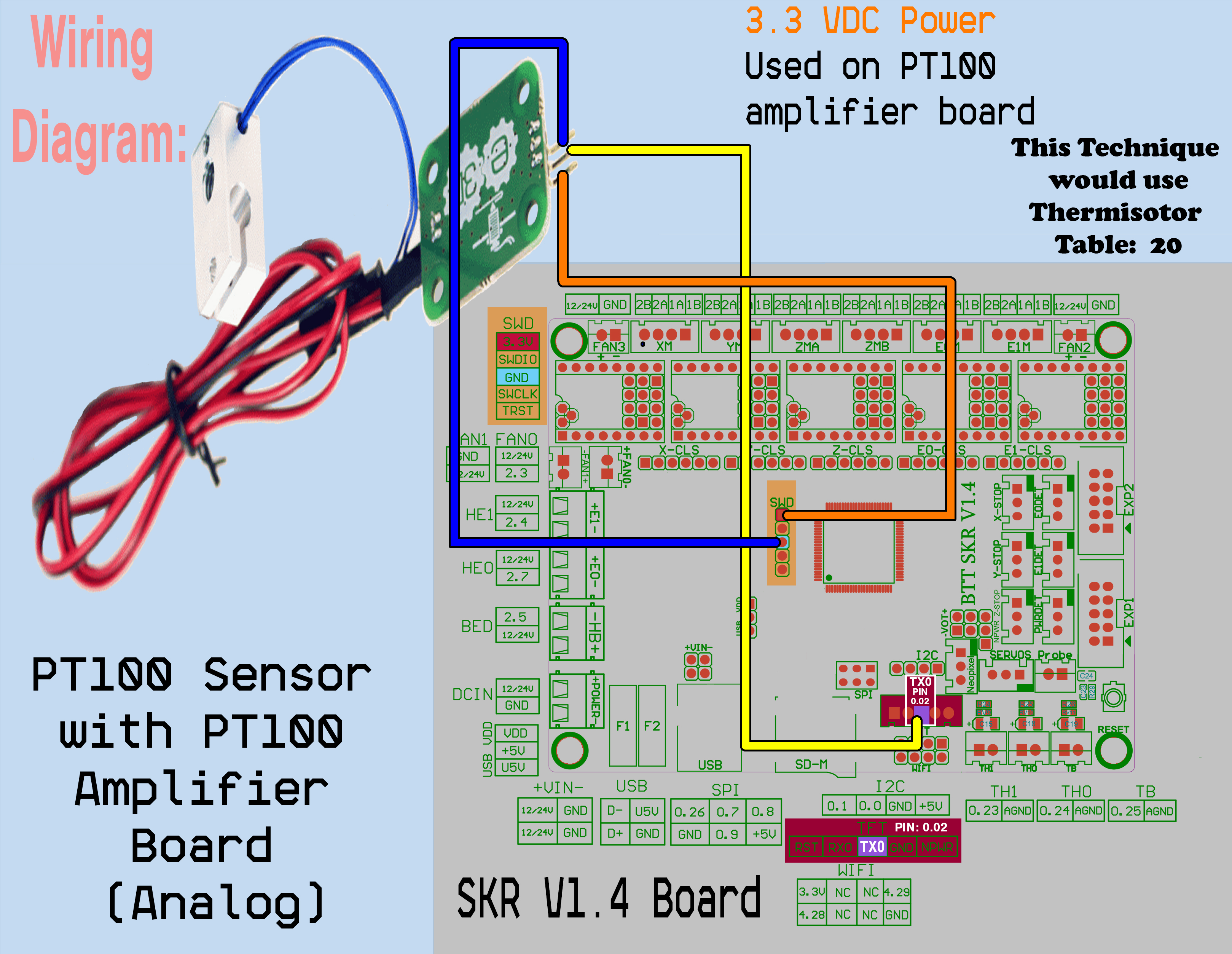
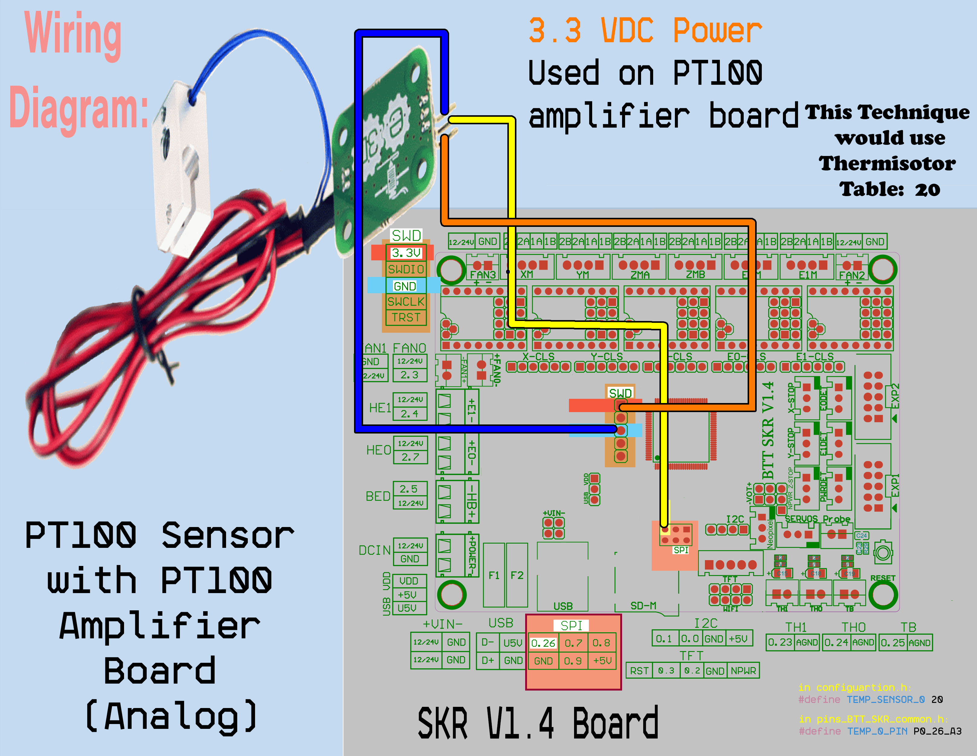
- Use table 20: When the power supply for the PT100/PT1000 Amplifier board is equal to the ADC reference voltage for the MCU. -- For SKR PRO V1.1/V1.2, SKR V1.3/V1.4/V1.4 Turbo, GTR V1.0, M5 V1.0 all use 3.3 VDC as the ADC reference voltage for the MCU. Therefore use table 20 when the PT100/PT1000 Amplifier board is powered by 3.3VDC
-
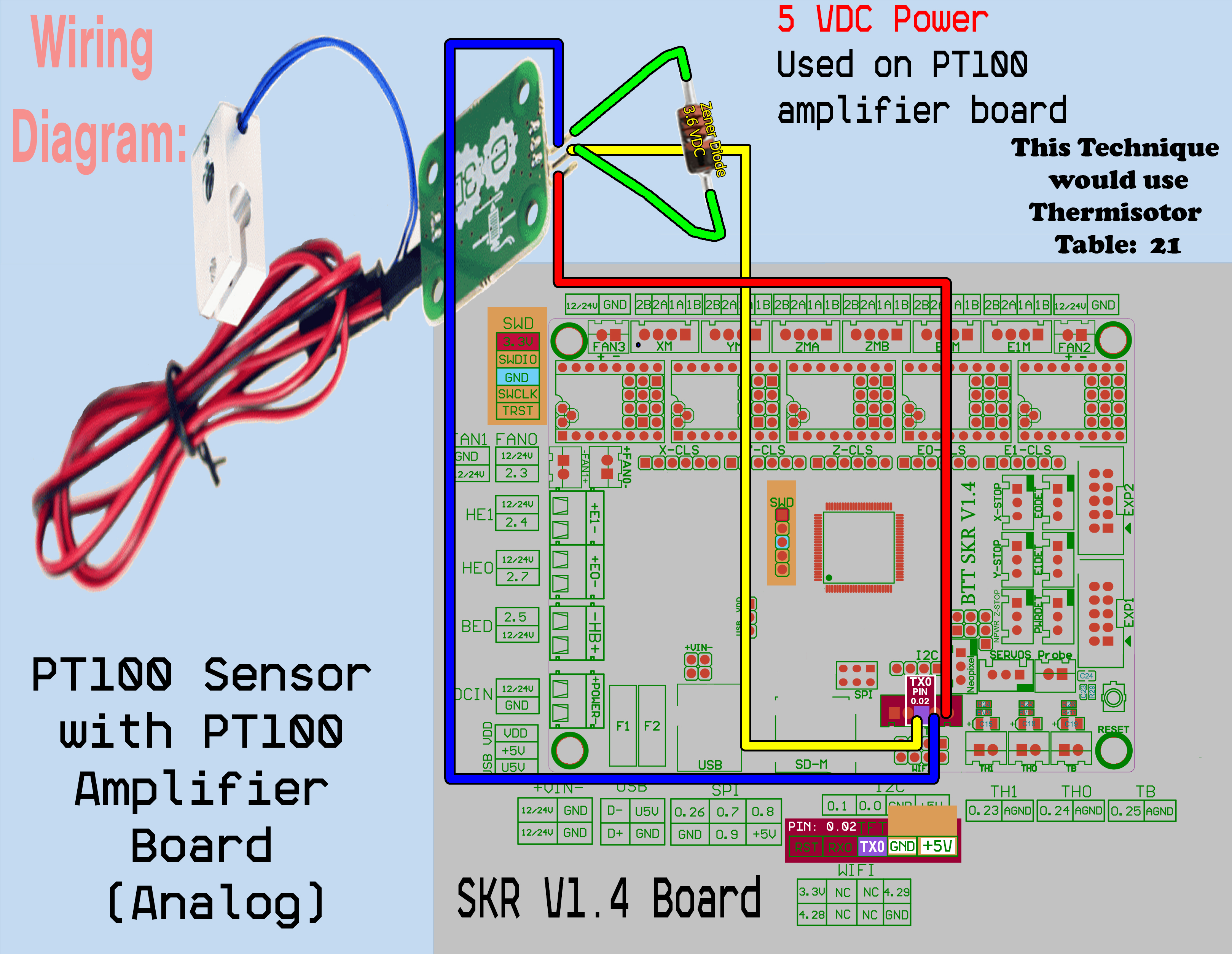
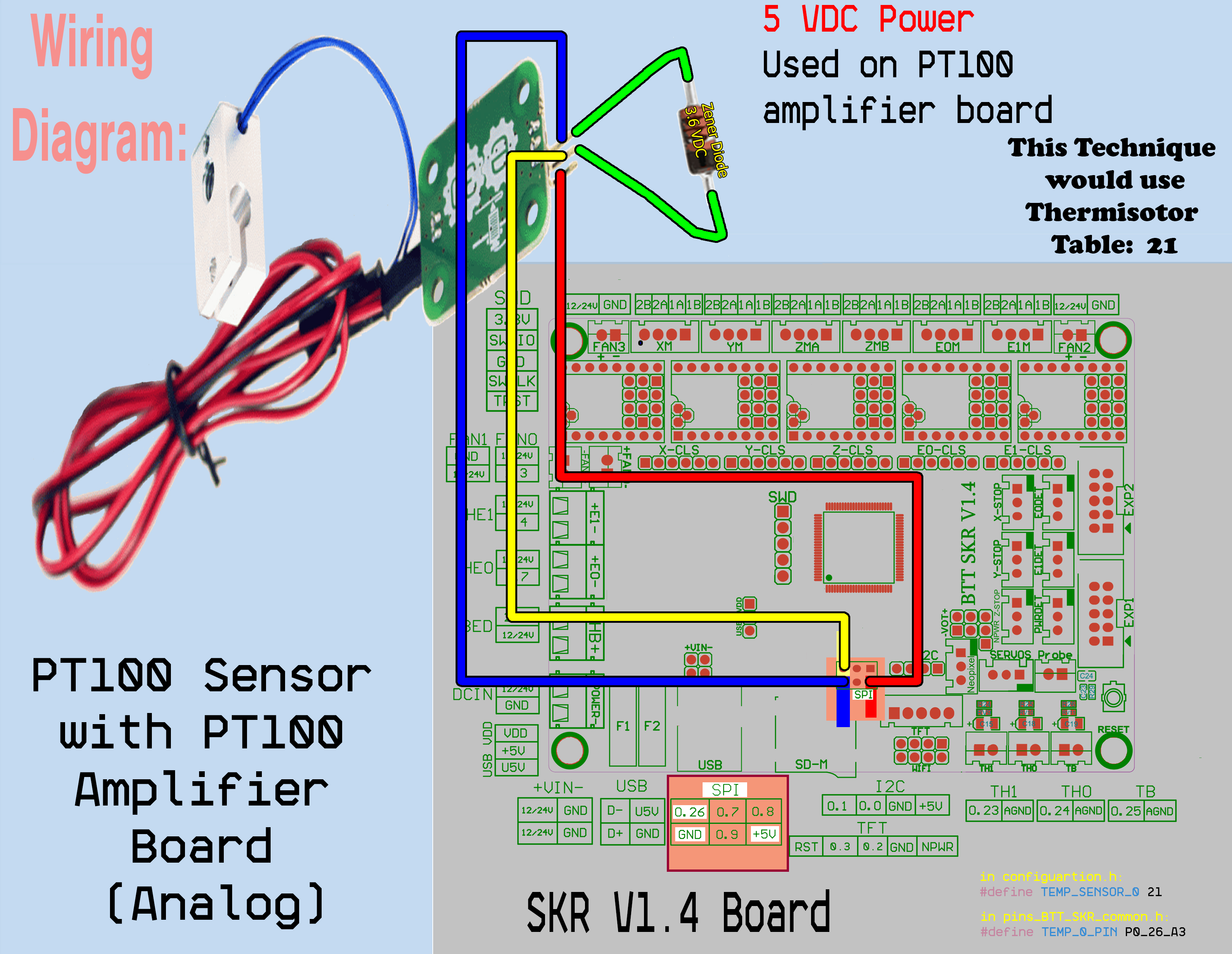
- Use table 21: When the power supply for the PT100/PT1000 Amplifier board is different to the ADC reference voltage for the MCU. -- The E3D PT100 Amplifier board wants 5V as its power supply. But the GTR V1.0 (like the SKR PRO) uses 3.3V as the ADC reference voltage for the MCU. If you use 5VDC power to the PT100 amplifier board, the amplifier can output a maximum signal with 5VDC. To protect the GTR V1.0 board (or the SKR PRO board), use a 3.6V Zener Diode (reverse biased hookup) between the output signal of the amplifier board and ground (to protect the MCU from getting fried from a 5V input).

The below wiring diagram for PT100 using Analog ADC input using 5V DC for the PT100 amplifier board but the MCU board (SKR V1.4 board) uses 3.3 VDC ADC reference voltage, therefore the Thermistor table to use for this is Table 21:
Analog Hook up of the E3D's PT100 Amplifier board to TFT conenctor on SKR V1.4 board using Thermistor Table 21:
This is for a hook up to the TFT connector and 5VDC power for the E3D PT100 amplifier board:
Analog Hook up of the E3D's PT100 Amplifier board to SPI header on SKR V1.4 board using Thermistor Table 21:
This is for a hook up to the SPI header and 5VDC power for the E3D PT100 amplifier board:
The below wiring diagram for PT100 using Analog ADC input using 3.3 VDC for the PT100 amplifier board but the MCU board (SKR V1.4 board) uses 3.3 VDC ADC reference voltage, therefore the Thermistor table to use for this is Table 20:
Analog Hook up of the E3D's PT100 Amplifier board to TFT conenctor on SKR V1.4 board using Thermistor Table 20:
This is for a hook up to the TFT connector and 3.3VDC power for the E3D PT100 amplifier board:
Analog Hook up of the E3D's PT100 Amplifier board to SPI header on SKR V1.4 board using Thermistor Table 20:
This is for a hook up to the SPI header and 3.3VDC power for the E3D PT100 amplifier board:
The information contained in [1, 4-14] are for the Adafruit MAX31865 board (PT100/PT1000 sensors) with the SKR V1.4 MCU board
- You can click on the below image and the browser will download the .jpg file or you can click on this URL address: https://github.com/GadgetAngel/MAX31865-SKR-V1-4-GUIDE/blob/main/images/General%20Information%20for%20SKR%20V1.4%20board%20Part1.jpg
In the below diagram, all the PINS in Yellow boxes are available on the SKR V1.4 board for use as digital I/O pins that the Marlin user can manipulate (the NOTES tell you when a PIN is available and when it it NOT available:
4A. For Marlin 2.0.7.1 or earlier versions of Marlin: If you want to use the Adafruit MAX31865 board with a PT100, you MUST correct the calibration resistor value that Marlin uses in temperature.cpp as follows: If you search in temperature.cpp for the string "max31865.temperature(", there are ONLY two places in temperature.cpp that will be found: Original is:
max31865.temperature(100, 400) // 100 ohms = PT100 resistance. 400 ohms = calibration resistor
CHANGE TO:
max31865.temperature(100, 430) // 100 ohms = PT100 resistance. 430 ohms = calibration resistor
4B. For Marlin 2.0.7.2: If you want to use the Adafruit MAX31865 boards with a PT100, you MUST use the Marlin variables in the configuration.h file to adjust the sensor resistance ohm value and calibration resistance ohm value as shown below. If they are not present in configuration.h file then you will need to add the two statements below to configuration.h file. Use the Marlin variables instead of making the change in the Marlin software in temperature.cpp as stated in 4A.
In configuration.h file:
// for TEMP_SENSOR_0:
#define MAX31865_SENSOR_OHMS 100
#define MAX31865_CALIBRATION_OHMS 430
4C. For Marlin bugfix-2.0.x branch or later versions of Marlin: If you want to use the Adafruit MAX31865 boards with a PT100, you MUST use the Marlin variables in the configuration.h file to adjust the sensor resistance ohm value and calibration resistance ohm value as shown below.
Use the Marlin variables instead of making the changes in the Marlin software in temperature.cpp as stated in 4A.
If you only have one (1) Adafruit MAX31865 board than use the Marlin variable MAX31865_SENSOR_OHMS_0 and Marlin variable MAX31865_CALIBRATION_OHMS_0 only (disable MAX31865_SENSOR_OHMS_1 and disable MAX31865_CALIBRATION_OHMS_1).
If you have two (2) Adafruit MAX31865 boards then enable all four Marlin variables: MAX31865_SENSOR_OHMS_0, MAX31865_CALIBRATION_OHMS_0, MAX31865_SENSOR_OHMS_1, and MAX31865_CALIBRATION_OHMS_1.
In configuration.h file:
// for TEMP_SENSOR_0:
#define MAX31865_SENSOR_OHMS_0 100
#define MAX31865_CALIBRATION_OHMS_0 430
// for TEMP_SENSOR_1:
#define MAX31865_SENSOR_OHMS_1 100
#define MAX31865_CALIBRATION_OHMS_1 430
5A. For Marlin 2.0.7.1 or earlier versions of Marlin: If you want to use the Adafruit MAX31865 board with a PT1000, you MUST correct the resistor values that Marlin uses in temperature.cpp as follows: If you search in temperature.cpp for the string "max31865.temperature(", there are ONLY two places in temperature.cpp that will be found: Original is:
max31865.temperature(100, 400) // 100 ohms = PT100 resistance. 400 ohms = calibration resistor
CHANGE TO:
max31865.temperature(1000, 4300) // 1000 ohms = PT1000 resistance. 4300 ohms = calibration resistor
5B. For Marlin 2.0.7.2: If you want to use the Adafruit MAX31865 boards with a PT1000, you MUST use the Marlin variables in the configuration.h file to adjust the sensor resistance ohm value and calibration resistance ohm value as shown below. If they are not present in configuration.h file then you will need to add the two statements below to configuration.h file. Use the Marlin variables instead of making the change in the Marlin software in temperature.cpp as stated in 5A.
In configuration.h file:
// for TEMP_SENSOR_0:
#define MAX31865_SENSOR_OHMS 1000
#define MAX31865_CALIBRATION_OHMS 4300
5C. For Marlin bugfix-2.0.x branch or later versions of Marlin: If you want to use the Adafruit MAX31865 boards with a PT1000, you MUST use the Marlin variables in the configuration.h file to adjust the sensor resistance ohm value and calibration resistance ohm value as shown below.
Use the Marlin variables instead of making the changes in the Marlin software in temperature.cpp as stated in 5A.
If you only have one (1) Adafruit MAX31865 board than use the Marlin variable MAX31865_SENSOR_OHMS_0 and Marlin variable MAX31865_CALIBRATION_OHMS_0 only (disable MAX31865_SENSOR_OHMS_1 and disable MAX31865_CALIBRATION_OHMS_1).
If you have two (2) Adafruit MAX31865 boards then enable all four Marlin variables: MAX31865_SENSOR_OHMS_0, MAX31865_CALIBRATION_OHMS_0, MAX31865_SENSOR_OHMS_1, and MAX31865_CALIBRATION_OHMS_1.
In configuration.h file:
// for TEMP_SENSOR_0:
#define MAX31865_SENSOR_OHMS_0 1000
#define MAX31865_CALIBRATION_OHMS_0 4300
// for TEMP_SENSOR_1:
#define MAX31865_SENSOR_OHMS_1 1000
#define MAX31865_CALIBRATION_OHMS_1 4300
- You must prepare the Adafruit MAX31865 board for 2_WIRE_MODE because that is the ONLY mode for the Adafruit MAX31865 board that Marlin supports.
Do the following to prepare the Adafruit MAX31865 board correctly:
You need to solder two bridges on the MAX31865 board. Marlin will only read an RTD which have 2-Wire configuration. (https://voron.dozuki.com/Guide/How+to+Use+a+Pt100+Thermistor+w-+Skr+Boards/73?lang=en). Ensure your PT100 is hooked to the middle two terminals.

- If you want to use the Adafruit MAX31865 board for PT100 sensor or PT1000 sensor with your SKR V1.4 board then ENSURE that the Adafruit MAX31865 library is my modified Adafruit MAX31865 library called Adafruit-MAX31865-V1.1.0-Mod-M by doing the following:
Check that in platformio.ini file the following line exists in [common] under lib_deps = and feature dependencies [features]:
MAX6675_._IS_MAX31865 = Adafruit MAX31865 library@~1.1.0
Change the line:
MAX6675_._IS_MAX31865 = Adafruit MAX31865 library@~1.1.0
to
MAX6675_._IS_MAX31865 = https://github.com/GadgetAngel/Adafruit-MAX31865-V1.1.0-Mod-M.git
Because the SKR V1.3/V1.4/V1.4 TURBO boards are part of the LPC framework for Marlin the current Adafruit MAX31865 V1.1.0 library will NOT COMPILE due to the LPC framework uses a different compile time constant called ARDUINOLPC instead of ARDUINO. I have tried using the Adafruit MAX31865 V1.1.0 libarary and setting the ARDUINO constant but there are TOO MANY compile time warnings. So my library "Adafruit-MAX31865-V1.1.0-Mod-M" incorporates the ARDUINOLPC constant which allows the Marlin user to COMPILE without warnings and to use the library. My library "Adafruit-MAX31865-V1.1.0-Mod-M" is the Adafruit MAX31865 V1.1.0 library with additional stuff to allow it to work with more than just the SKR V1.3/V1.4/V1.4T boards.
- Do I have a 100 ohm or 1000 ohm MAX31865 board? Here is how you tell:

-
If you want to use PT100 temperature sensor with the Adafruit MAX31865 over SPI you have two options:
A. Software SPI (where the MCU performs the handshake in software)
B. Hardware SPI (where the MCU performs the handshake with hardware interrupts).
-
If you want to use the Hardware SPI for Adafruit MAX31865, then you have to know which SPI bus on the MCU board is the default hardware SPI bus (SPI Bus 0 or SPI Bus 1 or SPI Bus 2) due to the fact that the Adafruit MAX31865 Library will default to this bus (Adafruit MAX31865 library does not expose the bus number, so it just defaults).
11A. How to determine the default hardware SPI bus for a the SKR boards: To determine the default hardware SPI bus for BTT SKR boards, look at the following Marlin variable:
- SDCARD_CONNECTION in your boards pins_[your board].h file
- SDSUPPORT in configuration.h file
- SDCARD_CONNECTION in configuration_adv.h file
In the pins-file (Marlin\src\pins) for the board, look for the following Marlin variables:
//
// SD Support
//

#ifndef SDCARD_CONNECTION
  #define SDCARD_CONNECTION                  LCD
#endif
and in configuration.h file:
/**
 * SD CARD
 *
 * SD Card support is disabled by default. If your controller has an SD slot,
 * you must uncomment the following option or it won't work.
 */
#define SDSUPPORT
and in configuratio_adv.h file:
  /**
   * Set this option to one of the following (or the board's defaults apply):
   *
   *           LCD - Use the SD drive in the external LCD controller.
   *       ONBOARD - Use the SD drive on the control board. (No SD_DETECT_PIN. M21 to init.)
   *  CUSTOM_CABLE - Use a custom cable to access the SD (as defined in a pins file).
   *
   * :[ 'LCD', 'ONBOARD', 'CUSTOM_CABLE' ]
   */
  //#define SDCARD_CONNECTION LCD
Below is a table which indicates the default hardware SPI bus, or connector, for the BTT SKR series of boards:
     board                      pins-file                              SDCARD_CONNECTION setting                      default HW SPI BUS number
---------------           ------------------                       -------------------------------                    --------------------------
SKR-mini-V1.1.............pins_BTT_SKR_MINI_V1_1.h.............................ONBOARD.............................................1 (micro SD card reader)  when SDSUPPORT is enabled or disabled in configuration.h file as long as ONBOARD_SPI_DEVICE in pins_BTT_SKR_MINI_V1_1.h is set to 1; Use JSER Micro SD TF Memory Card Kit Male to Female Extension Adapter (https://www.amazon.com/gp/product/B071DKCK47/).  When you have a device hooked up to the micro-SD card reader, disconnect the power to the MAX temperature sensor board  (remove GND and VIN from the MAX board) when doing a firmware update via the micro-SD card reader.  If you do not disconnect the power your micro-SD card can become corrupted. To over come the fact that BTT put a pull-up resistor on the SCLK line of the micro-SD card reader you might have to add a compile directive to tell the software to use SPI_MODE3 instead of SPI_MODE0.  This feature has not yet been added to the bugfix branch of Marlin.  But be aware that for the MAX31855 and MA31865 boards you will need to use SPI_MODE3 when using hardware SPI, for the MAX6675 you will need to use SPI_MODE2 when using hardware SPI.
SKR-mini-V1.1.............pins_BTT_SKR_MINI_V1_1.h.............................LCD.................................................1 (mico SD card reader) NOTE: SDSUPPORT is disabled in configuration.h file as long as ONBOARD_SPI_DEVICE in pins_BTT_SKR_MINI_V1_1.h is set to 1. Use JSER Micro SD TF Memory Card Kit Male to Female Extension Adapter (https://www.amazon.com/gp/product/B071DKCK47/).  When you have a device hooked up to the micro-SD card reader, disconnect the power to the MAX temperature sensor board  (remove GND and VIN from the MAX board) when doing a firmware update via the micro-SD card reader.  If you do not disconnect the power your micro-SD card can become corrupted. To over come the fact that BTT put a pull-up resistor on the SCLK line of the micro-SD card reader you might have to add a compile directive to tell the software to use SPI_MODE3 instead of SPI_MODE0.  This feature has not yet been added to the bugfix branch of Marlin.  But be aware that for the MAX31855 and MA31865 boards you will need to use SPI_MODE3 when using hardware SPI, for the MAX6675 you will need to use SPI_MODE2 when using hardware SPI.
SKR-mini-V1.1.............pins_BTT_SKR_MINI_V1_1.h.............................LCD.................................................3 (EXP2) NOTE: SDSPPORT is enabled in configruation.h file. Use EXP2 clamp on ribbon cable connector from https://www.digikey.com/product-detail/en/te-connectivity-amp-connectors/1658622-1/AKC10B-ND/825411 to acess the EXP2 SPI lines. The following EXP2 pins are used: PB3 as SCLK, PB4 as MISO and PB5 as MOSI
SKR mini E3 V1.0..........pins_BTT_SKR_MINI_E3_common.h........................ONBOARD.............................................1 (micro SD card reader)  when SDSUPPORT is enabled or disabled in configuration.h file as long as ONBOARD_SPI_DEVICE in pins_BTT_SKR_MINI_E3_common.h is set to 1(look at Marlin\src\HAL\STM32F1\spi_pins.h file; "1" means you are using PA5 as SCLK, PA6 as MISO and PA7 as MOSI.); Use SPI1 header PINS.  When you have a device hooked up to the SPI header pins, disconnect the power to the MAX temperature sensor board  (remove GND and VIN from the MAX board) when doing a firmware update via the micro-SD card reader.  If you do not disconnect the power your micro-SD card can become corrupted. To over come the fact that BTT put a pull-up resistor on the SCLK line of the micro-SD card reader you might have to add a compile directive to tell the software to use SPI_MODE3 instead of SPI_MODE0.  This feature has not yet been added to the bugfix branch of Marlin.  But be aware that for the MAX31855 and MA31865 boards you will need to use SPI_MODE3 when using hardware SPI, for the MAX6675 you will need to use SPI_MODE2 when using hardware SPI.
SKR mini E3 V1.0..........pins_BTT_SKR_MINI_E3_common.h........................LCD.................................................1 (micro SD card reader) NOTE: SDSUPPORT is enabled or disabled in configuration.h file as long as ONBOARD_SPI_DEVICE in pins_BTT_SKR_MINI_E3_common.h is set to 1(look at Marlin\src\HAL\STM32F1\spi_pins.h file; "1" means you are using PA5 as SCLK, PA6 as MISO and PA7 as MOSI.); Use SPI1 header PINS.  When you have a device hooked up to the SPI header pins, disconnect the power to the MAX temperature sensor board  (remove GND and VIN from the MAX board) when doing a firmware update via the micro-SD card reader.  If you do not disconnect the power your micro-SD card can become corrupted. To over come the fact that BTT put a pull-up resistor on the SCLK line of the micro-SD card reader you might have to add a compile directive to tell the software to use SPI_MODE3 instead of SPI_MODE0.  This feature has not yet been added to the bugfix branch of Marlin.  But be aware that for the MAX31855 and MA31865 boards you will need to use SPI_MODE3 when using hardware SPI, for the MAX6675 you will need to use SPI_MODE2 when using hardware SPI.
SKR mini E3 V1.2..........pins_BTT_SKR_MINI_E3_common.h........................ONBOARD.............................................1 (micro SD card reader)  when SDSUPPORT is enabled or disabled in configuration.h file as long as ONBOARD_SPI_DEVICE in pins_BTT_SKR_MINI_E3_common.h is set to 1(look at Marlin\src\HAL\STM32F1\spi_pins.h file; "1" means you are using PA5 as SCLK, PA6 as MISO and PA7 as MOSI.); Use SPI1 header PINS.  When you have a device hooked up to the SPI header pins, disconnect the power to the MAX temperature sensor board  (remove GND and VIN from the MAX board) when doing a firmware update via the micro-SD card reader.  If you do not disconnect the power your micro-SD card can become corrupted. To over come the fact that BTT put a pull-up resistor on the SCLK line of the micro-SD card reader you might have to add a compile directive to tell the software to use SPI_MODE3 instead of SPI_MODE0.  This feature has not yet been added to the bugfix branch of Marlin.  But be aware that for the MAX31855 and MA31865 boards you will need to use SPI_MODE3 when using hardware SPI, for the MAX6675 you will need to use SPI_MODE2 when using hardware SPI.
SKR mini E3 V1.2..........pins_BTT_SKR_MINI_E3_common.h........................LCD.................................................1 (micro SD card reader) NOTE: SDSUPPORT is enabled or disabled in configuration.h file as long as ONBOARD_SPI_DEVICE in pins_BTT_SKR_MINI_E3_common.h is set to 1(look at Marlin\src\HAL\STM32F1\spi_pins.h file; "1" means you are using PA5 as SCLK, PA6 as MISO and PA7 as MOSI.); Use SPI1 header PINS.  When you have a device hooked up to the SPI header pins, disconnect the power to the MAX temperature sensor board  (remove GND and VIN from the MAX board) when doing a firmware update via the micro-SD card reader.  If you do not disconnect the power your micro-SD card can become corrupted. To over come the fact that BTT put a pull-up resistor on the SCLK line of the micro-SD card reader you might have to add a compile directive to tell the software to use SPI_MODE3 instead of SPI_MODE0.  This feature has not yet been added to the bugfix branch of Marlin.  But be aware that for the MAX31855 and MA31865 boards you will need to use SPI_MODE3 when using hardware SPI, for the MAX6675 you will need to use SPI_MODE2 when using hardware SPI.
SKR mini E3 V2.0..........pins_BTT_SKR_MINI_E3_common.h........................LCD.................................................1 (micro SD card reader) NOTE: SDSUPPORT is enabled or disabled in configuration.h file as long as ONBOARD_SPI_DEVICE in pins_BTT_SKR_MINI_E3_common.h is set to 1(look at Marlin\src\HAL\STM32F1\spi_pins.h file; "1" means you are using PA5 as SCLK, PA6 as MISO and PA7 as MOSI.); Use SPI1 header PINS.  When you have a device hooked up to the SPI header pins, disconnect the power to the MAX temperature sensor board  (remove GND and VIN from the MAX board) when doing a firmware update via the micro-SD card reader.  If you do not disconnect the power your micro-SD card can become corrupted. To over come the fact that BTT put a pull-up resistor on the SCLK line of the micro-SD card reader you might have to add a compile directive to tell the software to use SPI_MODE3 instead of SPI_MODE0.  This feature has not yet been added to the bugfix branch of Marlin.  But be aware that for the MAX31855 and MA31865 boards you will need to use SPI_MODE3 when using hardware SPI, for the MAX6675 you will need to use SPI_MODE2 when using hardware SPI.
SKR mini E3 V2.0..........pins_BTT_SKR_MINI_E3_common.h........................ONBOARD.............................................1 (micro SD card reader)  when SDSUPPORT is enabled or disabled in configuration.h file as long as ONBOARD_SPI_DEVICE in pins_BTT_SKR_MINI_E3_common.h is set to 1(look at Marlin\src\HAL\STM32F1\spi_pins.h file; "1" means you are using PA5 as SCLK, PA6 as MISO and PA7 as MOSI.); Use SPI1 header PINS.  When you have a device hooked up to the SPI header pins, disconnect the power to the MAX temperature sensor board  (remove GND and VIN from the MAX board) when doing a firmware update via the micro-SD card reader.  If you do not disconnect the power your micro-SD card can become corrupted. To over come the fact that BTT put a pull-up resistor on the SCLK line of the micro-SD card reader you might have to add a compile directive to tell the software to use SPI_MODE3 instead of SPI_MODE0.  This feature has not yet been added to the bugfix branch of Marlin.  But be aware that for the MAX31855 and MA31865 boards you will need to use SPI_MODE3 when using hardware SPI, for the MAX6675 you will need to use SPI_MODE2 when using hardware SPI.
SKR mini MZ V1.0..........pins_BTT_SKR_MINI_E3_common.h........................ONBOARD.............................................1 (micro SD card reader)  when SDSUPPORT is enabled or disabled in configuration.h file as long as ONBOARD_SPI_DEVICE in pins_BTT_SKR_MINI_E3_common.h is set to 1(look at Marlin\src\HAL\STM32F1\spi_pins.h file; "1" means you are using PA5 as SCLK, PA6 as MISO and PA7 as MOSI.); Use JSER Micro SD TF Memory Card Kit Male to Female Extension Adapter (https://www.amazon.com/gp/product/B071DKCK47/). When you have a device is hooked up to the micro-SD card reader, disconnect the power to the MAX temperature sensor board  (remove GND and VIN from the MAX board) when doing a firmware update via the micro-SD card reader.  If you do not disconnect the power your micro-SD card can become corrupted. To over come the fact that BTT put a pull-up resistor on the SCLK line of the micro-SD card reader you might have to add a compile directive to tell the software to use SPI_MODE3 instead of SPI_MODE0.  This feature has not yet been added to the bugfix branch of Marlin.  But be aware that for the MAX31855 and MA31865 boards you will need to use SPI_MODE3 when using hardware SPI, for the MAX6675 you will need to use SPI_MODE2 when using hardware SPI.
SKR mini MZ V1.0..........pins_BTT_SKR_MINI_E3_common.h........................LCD.................................................1 (micro SD card reader) NOTE: SDSUPPORT is enabled or disabled in configuration.h file as long as ONBOARD_SPI_DEVICE in pins_BTT_SKR_MINI_E3_common.h is set to 1(look at Marlin\src\HAL\STM32F1\spi_pins.h file; "1" means you are using PA5 as SCLK, PA6 as MISO and PA7 as MOSI.); Use JSER Micro SD TF Memory Card Kit Male to Female Extension Adapter (https://www.amazon.com/gp/product/B071DKCK47/). When you have a device is hooked up to the micro-SD card reader, disconnect the power to the MAX temperature sensor board  (remove GND and VIN from the MAX board) when doing a firmware update via the micro-SD card reader.  If you do not disconnect the power your micro-SD card can become corrupted.  To over come the fact that BTT put a pull-up resistor on the SCLK line of the micro-SD card reader you might have to add a compile directive to tell the software to use SPI_MODE3 instead of SPI_MODE0.  This feature has not yet been added to the bugfix branch of Marlin.  But be aware that for the MAX31855 and MA31865 boards you will need to use SPI_MODE3 when using hardware SPI, for the MAX6675 you will need to use SPI_MODE2 when using hardware SPI.
SKR E3 DIP V1.0...........pins_BTT_SKR_E3_DIP.h................................ONBOARD.............................................1 (micro SD card reader)  when SDSUPPORT is enabled or disabled in configuration.h file as long as ONBOARD_SPI_DEVICE in pins_BTT_SKR_E3_DIP.h is set to 1(look at Marlin\src\HAL\STM32F1\spi_pins.h file; "1" means you are using PA5 as SCLK, PA6 as MISO and PA7 as MOSI.); Use SPI1 header PINS.  When you have a device hooked up to the SPI header pins, disconnect the power to the MAX temperature sensor board  (remove GND and VIN from the MAX board) when doing a firmware update via the micro-SD card reader.  If you do not disconnect the power your micro-SD card can become corrupted. To over come the fact that BTT put a pull-up resistor on the SCLK line of the micro-SD card reader you might have to add a compile directive to tell the software to use SPI_MODE3 instead of SPI_MODE0.  This feature has not yet been added to the bugfix branch of Marlin.  But be aware that for the MAX31855 and MA31865 boards you will need to use SPI_MODE3 when using hardware SPI, for the MAX6675 you will need to use SPI_MODE2 when using hardware SPI.
SKR E3 DIP V1.0...........pins_BTT_SKR_E3_DIP.h................................LCD.................................................1 (micro SD card reader) NOTE: SDSUPPORT is enabled or disabled in configuration.h file as long as ONBOARD_SPI_DEVICE in pins_BTT_SKR_E3_DIP.h is set to 1(look at Marlin\src\HAL\STM32F1\spi_pins.h file; "1" means you are using PA5 as SCLK, PA6 as MISO and PA7 as MOSI.); Use SPI1 header PINS.  When you have a device hooked up to the SPI header pins, disconnect the power to the MAX temperature sensor board  (remove GND and VIN from the MAX board) when doing a firmware update via the micro-SD card reader.  If you do not disconnect the power your micro-SD card can become corrupted. To over come the fact that BTT put a pull-up resistor on the SCLK line of the micro-SD card reader you might have to add a compile directive to tell the software to use SPI_MODE3 instead of SPI_MODE0.  This feature has not yet been added to the bugfix branch of Marlin.  But be aware that for the MAX31855 and MA31865 boards you will need to use SPI_MODE3 when using hardware SPI, for the MAX6675 you will need to use SPI_MODE2 when using hardware SPI.
SKR CR6...................pins_BTT_SKR_CR6.h...................................ONBOARD.............................................1 (SD card reader)  when SDSUPPORT is enabled or disabled in configuration.h file (look at Marlin\src\HAL\STM32F1\spi_pins.h file; "1" means you are using PA5 as SCLK, PA6 as MISO and PA7 as MOSI.); Use SanDisk MicroSD to SD Memory Card Adapter (https://www.amazon.com/SanDisk-microSD-Memory-Adapter-MICROSD-ADAPTER/dp/B0047WZOOO) and this instructable to help gain access to the SPI lines for the SD card reader (https://www.instructables.com/How-to-make-an-SD-Card-extension/). When you have a device is hooked up to the micro-SD card reader, disconnect the power to the MAX temperature sensor board  (remove GND and VIN from the MAX board) when doing a firmware update via the micro-SD card reader.  If you do not disconnect the power your micro-SD card can become corrupted. To over come the fact that BTT put a pull-up resistor on the SCLK line of the micro-SD card reader you might have to add a compile directive to tell the software to use SPI_MODE3 instead of SPI_MODE0.  This feature has not yet been added to the bugfix branch of Marlin.  But be aware that for the MAX31855 and MA31865 boards you will need to use SPI_MODE3 when using hardware SPI, for the MAX6675 you will need to use SPI_MODE2 when using hardware SPI.
SKR CR6...................pins_BTT_SKR_CR6.h...................................LCD.................................................1 (SD card reader) NOTE: SDSUPPORT is enabled or disabled in configuration.h file (look at Marlin\src\HAL\STM32F1\spi_pins.h file; "1" means you are using PA5 as SCLK, PA6 as MISO and PA7 as MOSI.); Use SanDisk MicroSD to SD Memory Card Adapter (https://www.amazon.com/SanDisk-microSD-Memory-Adapter-MICROSD-ADAPTER/dp/B0047WZOOO) and this instructable to help gain access to the SPI lines for the SD card reader (https://www.instructables.com/How-to-make-an-SD-Card-extension/). When you have a device is hooked up to the micro-SD card reader, disconnect the power to the MAX temperature sensor board  (remove GND and VIN from the MAX board) when doing a firmware update via the micro-SD card reader.  If you do not disconnect the power your micro-SD card can become corrupted.  To over come the fact that BTT put a pull-up resistor on the SCLK line of the micro-SD card reader you might have to add a compile directive to tell the software to use SPI_MODE3 instead of SPI_MODE0.  This feature has not yet been added to the bugfix branch of Marlin.  But be aware that for the MAX31855 and MA31865 boards you will need to use SPI_MODE3 when using hardware SPI, for the MAX6675 you will need to use SPI_MODE2 when using hardware SPI.
SKR E3 TURBO..............pins_BTT_SKR_E3_TURBO.h..............................ONBOARD.............................................0 (EXP1) NOTE: when SDSUPPORT is disabled in configuration.h file.  P0_15 is SPI SCLK line, P0_17 is SPI MISO line and P0_18 is SPI MOSI line; see the SKR_E3_TURBO_PIN diagram(https://github.com/bigtreetech/BIGTREETECH-SKR-E3-Turbo/blob/master/Hardware/BTT%20SKR%20E3%20Turbo-Pin.pdf) for location on the EXP1 connector.
SKR E3 TURBO..............pins_BTT_SKR_E3_TURBO.h..............................ONBOARD.............................................1 (micro SD card reader) NOTE: ONLY when SDSUPPORT is enabled in configuration.h file. Use JSER Micro SD TF Memory Card Kit Male to Female Extension Adapter (https://www.amazon.com/gp/product/B071DKCK47/).   Since the micro SD card Reader on the SKR E3 TURBO uses a pull-up resistor on the SCLK line you need to use the `-DTEMP_MODE=3` compile flag to tell the MAX31865 library to use SPI_MODE3 instead of SPI_MODE0.  This compile flag has NOT been implemented in the Adafruit MAX31865 library Version 1.1.0 so you will need to use my MAX31865 library called Adafruit-MAX31865-V1.1.0-Mod-M. To use Adafruit-MAX31865-V1.1.0-Mod-M library in platformio.ini file replace MAX6675_._IS_MAX31865   = Adafruit MAX31865 library@~1.1.0 with MAX6675_._IS_MAX31865   = https://github.com/GadgetAngel/Adafruit-MAX31865-V1.1.0-Mod-M.git then add the compile flag -DTEMP_MODE=3 by going to platformio.ini file and find [common_LPC]. In [common_LPC] the build flags line should look like the following: build_flags       = ${common.build_flags} -DU8G_HAL_LINKS -IMarlin/src/HAL/LPC1768/include -IMarlin/src/HAL/LPC1768/u8g -DTEMP_MODE=3.  When updating firmware, remove the Extension Adapter, place your SD card in the reader and reboot so the new firmware will be uploaded to the SKR E3 TURBO board. If you get a MIN TEMP error ignore it and power off the printer. Now, reinsert the Extension Adapter back into the SD card reader.  Turn power on to the printer and you should still have a good temperature reading as long as your firmware changes did not effect the MAX board.
SKR E3 TURBO..............pins_BTT_SKR_E3_TURBO.h..............................LCD.................................................0 (EXP1) NOTE: when SDSUPPORT is disabled in configuration.h file. P0_15 is SPI SCLK line, P0_17 is SPI MISO line and P0_18 is SPI MOSI line; see the SKR_E3_TURBO_PIN diagram(https://github.com/bigtreetech/BIGTREETECH-SKR-E3-Turbo/blob/master/Hardware/BTT%20SKR%20E3%20Turbo-Pin.pdf) for location on the EXP1 connector.
SKR E3 TURBO..............pins_BTT_SKR_E3_TURBO.h..............................LCD.................................................0 (EXP1) NOTE: when SDSUPPORT is enabled in configuration.h file. P0_15 is SPI SCLK line, P0_17 is SPI MISO line and P0_18 is SPI MOSI line; see the SKR_E3_TURBO_PIN diagram(https://github.com/bigtreetech/BIGTREETECH-SKR-E3-Turbo/blob/master/Hardware/BTT%20SKR%20E3%20Turbo-Pin.pdf) for location on the EXP1 connector.
SKR V1.3..................pins_BTT_SKR_V1_3.h..................................LCD.................................................0 (EXP2) NOTE: SDSUPPORT is enabled or disabled in configuration.h file. Use EXP2 clamp on ribbon cable connector from https://www.digikey.com/product-detail/en/te-connectivity-amp-connectors/1658622-1/AKC10B-ND/825411 to acess the EXP2 SPI lines.
SKR V1.3..................pins_BTT_SKR_V1_3.h..................................ONBOARD.............................................0 (EXP2) ONLY when SDSUPPORT is disabled in configuration.h file. Use EXP2 clamp on ribbon cable connector from https://www.digikey.com/product-detail/en/te-connectivity-amp-connectors/1658622-1/AKC10B-ND/825411 to acess the EXP2 SPI lines.
SKR V1.3..................pins_BTT_SKR_V1_3.h..................................ONBOARD.............................................1 (micro SD card reader) ONLY when SDSUPPORT is enabled in configuration.h file; Use JSER Micro SD TF Memory Card Kit Male to Female Extension Adapter (https://www.amazon.com/gp/product/B071DKCK47/).  When updating firmware, remove the Extension Adapter, place your SD card in the reader and reboot so the new firmware will be uploaded to the SKR V1.3 board. If you get a MIN TEMP error ignore it and power off the printer. Now, reinsert the Extension Adapter back into the SD card reader.  Turn power on to the printer and you should still have a good temperature reading as long as your firmware changes did not effect the MAX board. To over come the fact that BTT put a pull-up resistor on the SCLK line of the SD card reader you might have to add a compile directive to tell the software to use SPI_MODE3 instead of SPI_MODE0.  This feature has not yet been added to the bugfix branch of Marlin.  But be aware that for the MAX31855 and MA31865 boards you will need to use SPI_MODE3 when using hardware SPI, for the MAX6675 you will need to use SPI_MODE2 when using hardware SPI.
SKR V1.4..................pins_BTT_SKR_V1_4.h..................................LCD.................................................0 (EXP2) NOTE: SDSUPPORT is enabled or disabled in configuration.h file. Use EXP2 clamp on ribbon cable connector from https://www.digikey.com/product-detail/en/te-connectivity-amp-connectors/1658622-1/AKC10B-ND/825411 to acess the EXP2 SPI lines.
SKR V1.4..................pins_BTT_SKR_V1_4.h..................................ONBOARD.............................................0 (EXP2) NOTE: ONLY when SDSUPPORT is disabled in configuration.h file. Use EXP2 clamp on ribbon cable connector from https://www.digikey.com/product-detail/en/te-connectivity-amp-connectors/1658622-1/AKC10B-ND/825411 to acess the EXP2 SPI lines.
SKR V1.4..................pins_BTT_SKR_V1_4.h..................................ONBOARD.............................................1 (SPI header) NOTE: ONLY when SDSUPPORT is enabled in configuration.h file
SKR V1.4 Turbo............pins_BTT_SKR_V1_4.h..................................LCD.................................................0 (EXP2) NOTE: SDSUPPORT is enabled or disabled in configuration.h file. Use EXP2 clamp on ribbon cable connector from https://www.digikey.com/product-detail/en/te-connectivity-amp-connectors/1658622-1/AKC10B-ND/825411 to acess the EXP2 SPI lines.
SKR V1.4 Turbo............pins_BTT_SKR_V1_4.h.................................ONBOARD..............................................0 (EXP2) NOTE: ONLY when SDSUPPORT is disabled in configuration.h file. Use EXP2 clamp on ribbon cable connector from https://www.digikey.com/product-detail/en/te-connectivity-amp-connectors/1658622-1/AKC10B-ND/825411 to acess the EXP2 SPI lines.
SKR V1.4 Turbo............pins_BTT_SKR_V1_4.h.................................ONBOARD..............................................1 (SPI header) NOTE: ONLY when SDSUPPORT is enabled in configuration.h file.  To over come the fact that BTT put a pull-up resistor on the SCLK line of the SD card reader you might have to add a compile directive to tell the software to use SPI_MODE3 instead of SPI_MODE0.  This feature has not yet been added to the bugfix branch of Marlin.  But be aware that for the MAX31855 and MA31865 boards you will need to use SPI_MODE3 when using hardware SPI, for the MAX6675 you will need to use SPI_MODE2 when using hardware SPI.
SKR PRO V1.x..............pins_BTT_SKR_PRO_common.h............................LCD.................................................2 (EXP2) NOTE: when SDSUPPORT is disabled in configuration.h file. Use EXP2 clamp on ribbon cable connector from https://www.digikey.com/product-detail/en/te-connectivity-amp-connectors/1658622-1/AKC10B-ND/825411 to acess the EXP2 SPI lines.
SKR PRO V1.x..............pins_BTT_SKR_PRO_common.h............................LCD.................................................2 (EXP2) NOTE: when SDSUPPORT is enabled in configuration.h file. Use EXP2 clamp on ribbon cable connector from https://www.digikey.com/product-detail/en/te-connectivity-amp-connectors/1658622-1/AKC10B-ND/825411 to acess the EXP2 SPI lines.
SKR PRO V1.x..............pins_BTT_SKR_PRO_common.h............................ONBOARD.............................................2 (EXP2) NOTE: when SDSUPPORT is disabled in configuration.h file. Use EXP2 clamp on ribbon cable connector from https://www.digikey.com/product-detail/en/te-connectivity-amp-connectors/1658622-1/AKC10B-ND/825411 to acess the EXP2 SPI lines.
SKR PRO V1.x..............pins_BTT_SKR_PRO_common.h............................ONBOARD.............................................1 (micro SD card reader) NOTE: ONLY when SDSUPPORT is enabled in configuration.h file. Use JSER Micro SD TF Memory Card Kit Male to Female Extension Adapter (https://www.amazon.com/gp/product/B071DKCK47/).  When updating firmware, remove the Extension Adapter, place your SD card in the reader and reboot so the new firmware will be uploaded to the SKR PRO V1.x board. If you get a MIN TEMP error ignore it and power off the printer. Now, reinsert the Extension Adapter back into the SD card reader.  Turn power on to the printer and you should still have a good temperature reading as long as your firmware changes did not effect the MAX board.
GTR V1.0..................pins_BTT_GTR_V1_0.h..................................ONBOARD.............................................2 (EXP2) NOTE: when SDSUPPORT is disabled in configuration.h file. Use EXP2 clamp on ribbon cable connector from https://www.digikey.com/product-detail/en/te-connectivity-amp-connectors/1658622-1/AKC10B-ND/825411 to acess the EXP2 SPI lines.
GTR V1.0..................pins_BTT_GTR_V1_0.h..................................ONBOARD.............................................1 (micro SD card reader) NOTE: ONLY when SDSUPPORT is enabled in configuration.h file. Use JSER Micro SD TF Memory Card Kit Male to Female Extension Adapter (https://www.amazon.com/gp/product/B071DKCK47/).  When updating firmware, remove the Extension Adapter, place your SD card in the reader and reboot so the new firmware will be uploaded to the GTR V1.0 board. If you get a MIN TEMP error ignore it and power off the printer. Now, reinsert the Extension Adapter back into the SD card reader.  Turn power on to the printer and you should still have a good temperature reading as long as your firmware changes did not effect the MAX board.
GTR V1.0..................pins_BTT_GTR_V1_0.h..................................LCD.................................................2 (EXP2) NOTE: when SDSUPPORT is disabled in configuration.h file. Use EXP2 clamp on ribbon cable connector from https://www.digikey.com/product-detail/en/te-connectivity-amp-connectors/1658622-1/AKC10B-ND/825411 to acess the EXP2 SPI lines.
GTR V1.0..................pins_BTT_GTR_V1_0.h..................................LCD.................................................2 (EXP2) NOTE: when SDSUPPORT is enabled in configuration.h file. Use EXP2 clamp on ribbon cable connector from https://www.digikey.com/product-detail/en/te-connectivity-amp-connectors/1658622-1/AKC10B-ND/825411 to acess the EXP2 SPI lines.
BTT002 V1.0...............pins_BTT_BTT002_V1_0.h...........ONBOARD/LCD (this board does not have a micr SD card reader). ..........1 (EXP2) NOTE: SDSUPPORT is enabled or disabled in configuration.h file. Use EXP2 clamp on ribbon cable connector from https://www.digikey.com/product-detail/en/te-connectivity-amp-connectors/1658622-1/AKC10B-ND/825411 to acess the EXP2 SPI lines.
Some board's also have an additional file to check. In Marlin/buildroot/share/PlatformIO/variants/[board name]/variant.h file look for the following Marlin variables:
#define PIN_SPI_SCK
#define PIN_SPI_MISO
#define PIN_SPI_MOSI
If the board has both a variant.h file and a pins-file than Marlin first reads the variant.h file and then reads the pins-file. Therefore, the pins-file can override the default hardware SPI bus that the variant.h file defines. For example the SKR PRO V1.1 board, has two files to look through (variant.h and pins_BTT_SKR_PRO_common.h). The GTR V1.0 board has both files to look through. Let us look at an example. The GTR V1.0 board has the variant.h file which contains the following:
// Below SPI and I2C definitions already done in the core
// Could be redefined here if differs from the default one
// SPI Definitions
#define PIN_SPI_MOSI            PB15    //GADGETANGEL this is SPI2 (search the variant.h file for this PIN name and in the comment you will see the SPI bus number for this PIN)
#define PIN_SPI_MISO            PB14    //GADGETANGEL this is SPI2
#define PIN_SPI_SCK             PB13    //GADGETANGEL this is SPI2
#define PIN_SPI_SS              PB12
For the GTR V1.0 board the pins_BTT_GTR_V1_0.h contains the following:
#ifndef SDCARD_CONNECTION
  #define SDCARD_CONNECTION ONBOARD      //GADGETANGEL SD Card is set for ONBOARD which is SPI1(SD card reader) if SDSUPPORT is enabled in configuration.h file. If SDSUPPORT is DISABLED in configuration.h file than SPI2 (EXP2) is used.
#endif

//
// By default the LCD SD (SPI2) is enabled
// Onboard SD is on a completely separate SPI bus, and requires
// overriding pins to access.
//
#if SD_CONNECTION_IS(LCD)
  #define SD_DETECT_PIN                     PB10
  #define SDSS                              PB12               //GADGETANGEL this is SPI2, the same as the variant.h file
#elif SD_CONNECTION_IS(ONBOARD)
  // Instruct the STM32 HAL to override the default SPI pins from the variant.h file
  #define CUSTOM_SPI_PINS
  #define SDSS                              PA4
  #define SS_PIN                            SDSS
  #define SCK_PIN                           PA5                //GADGETANGEL this is SPI1 (search the variant.h file for this PIN name and in the comment you will see the SPI bus number for this PIN)
  #define MISO_PIN                          PA6                //GADGETANGEL this is SPI1
  #define MOSI_PIN                          PA7                //GADGETANGEL this is SPI1
  #define SD_DETECT_PIN                     PC4
#elif SD_CONNECTION_IS(CUSTOM_CABLE)
  #define "CUSTOM_CABLE is not a supported SDCARD_CONNECTION for this board"
#endif
Notice that for the GTR V1.0 board and SDSUPPORT enabled in configuration.h file, when Marlin executes, it will first set the default hardware SPI bus number to SPI2 due to the fact that the variables in variant.h get read in first. Then the file pins_BTT_GTR_V1_0.h gets read and it changes the default hardware SPI bus to SPI1. This is due to the Marlin variable "CUSTOM_SPI_PINS" and SDSUPPORT being enabled in configuration.h file, which is used to override the variant.h file SPI Marlin variables.
Additional Equipment that maybe necessary to obtain HARDWARE SPI for Adafruit MAX31865 with the SKR V1.4 board (MCU board)
11B. As stated in the above table for default hardware SPI bus you might need additional equipment to tap into the default hardware SPI lines. This section provides you links to find the extra equipment.
If you need to tap into the EXP2 flat ribbon cable use: https://www.digikey.com/product-detail/en/te-connectivity-amp-connectors/1658622-1/AKC10B-ND/825411 Orient the clamp on connector so that it is in the same orientation as the one already installed on the end of the flat ribbon cable that gets plugged into the EXP2 socket of the MCU board. This way you will be able to keep straight which PINs are which. I oriented mine to be upside down just like the connector that is already on the end that plugs into the EXP2 socket of the MCU board.
If you need to tap into the SD card reader ONBOARD the MCU board then use: JSER Micro SD TF Memory Card Kit Male to Female Extension Adapter (https://www.amazon.com/gp/product/B071DKCK47/) You will have to solder on three wires to the locations shown below and it only costs $4.00 on Amazon.com:

- If you want to use Hardware SPI for Adafruit MAX31865 (for PT100 or PT1000) then you must know which SPI bus will be the default hardware SPI bus for the board. For the SKR V1.4 board the default hardware SPI bus is EXP2 or SPI bus #0. You have to find a way to access the default hardware SPI bus' MOSI, MISO and SCK lines. To access these lines for the SKR V1.4 board, you have to use a clamp-on flat ribbon cable connector(https://www.digikey.com/product-detail/en/te-connectivity-amp-connectors/1658622-1/AKC10B-ND/825411)

++++++++++++++++++++++++++++++++EXAMPLE 1+++++++++++++++++++++++++++++++++++
To setup Marlin on SKR V1.4 board for Adafruit MAX31865 and Hardware SPI which occurs on the EXP2 connector, do the following:
Ensure in pins_BTT_SKR_V1_4.h file:
//
// SD Support
//

#ifndef SDCARD_CONNECTION
  #define SDCARD_CONNECTION                  LCD
#endif
Ensure in configuration.h file:
/**
 * SD CARD
 *
 * SD Card support is disabled by default. If your controller has an SD slot,
 * you must uncomment the following option or it won't work.
 */
#define SDSUPPORT   //this can be enabled or disabled to your wishes
Ensure in configuration_adv.h file:
  /**
   * Set this option to one of the following (or the board's defaults apply):
   *
   *           LCD - Use the SD drive in the external LCD controller.
   *       ONBOARD - Use the SD drive on the control board. (No SD_DETECT_PIN. M21 to init.)
   *  CUSTOM_CABLE - Use a custom cable to access the SD (as defined in a pins file).
   *
   * :[ 'LCD', 'ONBOARD', 'CUSTOM_CABLE' ]
   */
  //#define SDCARD_CONNECTION LCD    //this is set for LCD like it is in the pins_BTT_SKR_V1_4.h file, just incase this gets enabled. Leave it disabled for now
In platformio.ini file:
	default_envs = LPC1768
under [features] section of platformio.ini file:

	Replace

	MAX6675_._IS_MAX31865   = Adafruit MAX31865 library@~1.1.0

	With

	MAX6675_._IS_MAX31865    = https://github.com/GadgetAngel/Adafruit-MAX31865-V1.1.0-Mod-M.git

use the latest bugfix-2.0.x branch of Marlin (this will only work with the latest bugfix-2.0.x branch)

this is what the env:common_LPC needs to look like:

[common_LPC]
platform          = https://github.com/p3p/pio-nxplpc-arduino-lpc176x/archive/0.1.3.zip
platform_packages = framework-arduino-lpc176x@^0.2.6
board             = nxp_lpc1768
lib_ldf_mode      = off
lib_compat_mode   = strict
extra_scripts     = ${common.extra_scripts}
  Marlin/src/HAL/LPC1768/upload_extra_script.py
src_filter        = ${common.default_src_filter} +<src/HAL/LPC1768> +<src/HAL/shared/backtrace>
lib_deps          = ${common.lib_deps}
  Servo
custom_marlin.USES_LIQUIDCRYSTAL = [email protected]
custom_marlin.NEOPIXEL_LED = Adafruit NeoPixel=https://github.com/p3p/Adafruit_NeoPixel/archive/1.5.0.zip
build_flags       = ${common.build_flags} -DU8G_HAL_LINKS -IMarlin/src/HAL/LPC1768/include -IMarlin/src/HAL/LPC1768/u8g
  # debug options for backtrace
  #-funwind-tables
  #-mpoke-function-name
in pins_BTT_SKR_common.h :
Set TEMP_0_PIN to the CS pin you selected. In the below example I choose the EXP2 PIN P1_31.
#define TEMP_0_PIN P1_31
#define MAX6675_SS_PIN  TEMP_0_PIN
#define MAX31865_CS_PIN MAX6675_SS_PIN
//uncomment the next 2 lines if you have 2 boards
//#define MAX6675_SS2_PIN   P1_30
//#define MAX31865_CS2_PIN MAX6675_SS2_PIN
If you wanted two MAX31865 because you have two extruders on your printer I would use this HARDWARE SPI setup and then use EXP1 PIN P1_30 as the CS2 for the second MAX31865 board.
NOTE: Since the default Hardware SPI bus is now on the EXP1 and EXP2 connector the following PINS are not available for CS pin selection:
EXP2 PIN P0_15, this is the SPI SCK_PIN
EXP2 PIN P0_17, this is the SPI MISO_PIN
EXP2 PIN P0_18, this is the SPI MOSI_PIN
EXP2 PIN P0_16, this is the SPI SS_PIN for the LCD screen’s SD card reader.
in configuration_adv.h file:
In configuration_adv.h file:
#define MONITOR_DRIVER_STATUS
#define TMC_DEBUG
#define SHOW_TEMP_ADC_VALUES
#define MAX_CONSECUTIVE_LOW_TEMPERATURE_ERROR_ALLOWED 10
You will be using an TFT screen from BTT. It can be any TFT screen you like but the only requirement is that the TFT screen can run with the RS232 connector only. Most of the BTT TFT screens can run with only the TFT connector (or RS232, this limits the screen to using only the TFT screen or touch mode, the simulated 12864 LCD Marlin mode will NOT be available to you).
In configuration.h for the SKR V1.4 board:
#define SERIAL_PORT -1
#define SERIAL_PORT_2 0
#define BAUDRATE 115200
#define MOTHERBOARD BOARD_BTT_SKR_V1_4
#define EXTRUDERS 1
#define TEMP_SENSOR_0 -5
#define SDSUPPORT  //notice this is enabled or
                   //it can also be disabled

//#define REPRAP_DISCOUNT_FULL_GRAPHIC_SMART_CONTROLLER //notice this
                                                        //is disabled
//#define CR10_STOCKDISPLAY //notice this is disabled
For Marlin 2.0.7.1 or earlier version of Marlin: you have to change the code in temperature.cpp module as stated in 4A above.
OR
For Marlin 2.0.7.2 versions: ENABLE the following in configuration.h file or ADD the following lines to configuration.h file:
#define MAX31865_SENSOR_OHMS 100
#define MAX31865_CALIBRATION_OHMS 430
OR
For Marlin bugfix-2.0.x version or later versions of Marlin: ENABLE the following in configuration.h file:
#define MAX31865_SENSOR_OHMS_0 100
#define MAX31865_CALIBRATION_OHMS_0 430
//#define MAX31865_SENSOR_OHMS_1 100
//#define MAX31865_CALIBRATION_OHMS_1 430
Here is the wiring diagram for the Adafruit MAX31865 with PT100 via Hardware SPI on EXP2 connector for the SKR V1.4 board. To access the Hardware SPI lines for the SKR V1.4 board, you must use a tap for the EXP2 flat ribbon cable by using https://www.digikey.com/product-detail/en/te-connectivity-amp-connectors/1658622-1/AKC10B-ND/825411. Orient the clamp on connector so that it is in the same orientation as the one already installed on the end of the flat ribbon cable that gets plugged into the EXP2 socket of the SKR V1.4 board. This way you will be able to keep straight which PINs are which. I oriented mine to be upside down just like the connector that is already on the end that plugs into the EXP2 socket of the SKR V1.4 board.
You can click on the below image and the browser will download the .jpg file or you can click on this URL address: https://github.com/GadgetAngel/MAX31865-SKR-V1-4-GUIDE/blob/main/images/One%20PT100%20with%20One%20MAX31865%20boards%20in%20Hardware%20SPI%20with%20EXP2%20on%20SKR%20V1.4%20board%20_%20Wiring%20Diagram%20Part5.jpg
All the YELLOW boxes on the SKR V1.4 board are possible digital I/O pins that are available to use depending on what you have set in the Marlin firmware. The NOTES indicate when the PINS are available and when they are NOT available for use.
++++++++++++++++++++++++++++++++EXAMPLE 2+++++++++++++++++++++++++++++++++++
See NOTE4 if you plan on using Hardware SPI which shares the same bus as the ONBOARD micro-SD Card Reader (NOTE 4 is located in item number 4.)
To setup Marlin on SKR V1.4 board for Adafruit MAX31865 and Hardware SPI which occurs on the same bus as the ONBOARD micro-SD Card Reader, do the following:
set in pins_BTT_SKR_V1_4.h file:
//
// SD Support
//

#ifndef SDCARD_CONNECTION
  #define SDCARD_CONNECTION                  ONBOARD
#endif
set in configuration.h file:
/**
 * SD CARD
 *
 * SD Card support is disabled by default. If your controller has an SD slot,
 * you must uncomment the following option or it won't work.
 */
#define SDSUPPORT   //this MUST be enabled!! //if it is disabled, then your default SPI bus will point to EXP2 connector
set in configuration_adv.h file:
  /**
   * Set this option to one of the following (or the board's defaults apply):
   *
   *           LCD - Use the SD drive in the external LCD controller.
   *       ONBOARD - Use the SD drive on the control board. (No SD_DETECT_PIN. M21 to init.)
   *  CUSTOM_CABLE - Use a custom cable to access the SD (as defined in a pins file).
   *
   * :[ 'LCD', 'ONBOARD', 'CUSTOM_CABLE' ]
   */
  //#define SDCARD_CONNECTION ONBOARD    //this is set for ONBOARD like it is in the pins_BTT_SKR_V1_4.h file, just in case this gets enabled. Leave it disabled for now
In platformio.ini file:
	default_envs = LPC1768
under [features] section of platformio.ini file:

	Replace

	MAX6675_._IS_MAX31865   = Adafruit MAX31865 library@~1.1.0

	With

	MAX6675_._IS_MAX31865    = https://github.com/GadgetAngel/Adafruit-MAX31865-V1.1.0-Mod-M.git

use the latest bugfix-2.0.x branch of Marlin (this will only work with the latest bugfix-2.0.x branch)

this is what the env:common_LPC needs to look like (you are adding -DTEMP_MODE=3 build flag):

[common_LPC]
platform          = https://github.com/p3p/pio-nxplpc-arduino-lpc176x/archive/0.1.3.zip
platform_packages = framework-arduino-lpc176x@^0.2.6
board             = nxp_lpc1768
lib_ldf_mode      = off
lib_compat_mode   = strict
extra_scripts     = ${common.extra_scripts}
  Marlin/src/HAL/LPC1768/upload_extra_script.py
src_filter        = ${common.default_src_filter} +<src/HAL/LPC1768> +<src/HAL/shared/backtrace>
lib_deps          = ${common.lib_deps}
  Servo
custom_marlin.USES_LIQUIDCRYSTAL = [email protected]
custom_marlin.NEOPIXEL_LED = Adafruit NeoPixel=https://github.com/p3p/Adafruit_NeoPixel/archive/1.5.0.zip
build_flags       = ${common.build_flags} -DU8G_HAL_LINKS -IMarlin/src/HAL/LPC1768/include -IMarlin/src/HAL/LPC1768/u8g -DTEMP_MODE=3
  # debug options for backtrace
  #-funwind-tables
  #-mpoke-function-name
in pins_BTT_SKR_common.h file:
Set TEMP_0_PIN to the CS pin you selected. In the below example I choose the SPI header PIN P0_26.
#define TEMP_0_PIN P0_26
#define MAX6675_SS_PIN  TEMP_0_PIN
#define MAX31865_CS_PIN MAX6675_SS_PIN  //forces Hardware SPI to be used
In configuration_adv.h file:
#define MONITOR_DRIVER_STATUS
#define TMC_DEBUG
#define SHOW_TEMP_ADC_VALUES
#define MAX_CONSECUTIVE_LOW_TEMPERATURE_ERROR_ALLOWED 10
You will be using an TFT screen from BTT. It can be any TFT screen you like but the only requirement is that the TFT screen can run with the RS232 connector only. Most of the BTT TFT screens can run with only the TFT connector (or RS232, this limits the screen to using only the TFT screen or touch mode, the simulated 12864 LCD Marlin mode will NOT be available to you).
In configuration.h for the SKR V1.4 board:
#define SERIAL_PORT -1
#define SERIAL_PORT_2 0
#define BAUDRATE 115200
#define MOTHERBOARD BOARD_BTT_SKR_V1_4
#define EXTRUDERS 1
#define TEMP_SENSOR_0 -5
#define SDSUPPORT  //notice this is enabled,
                   //if this is disabled the SPI bus will be on EXP2
//#define REPRAP_DISCOUNT_FULL_GRAPHIC_SMART_CONTROLLER //notice this
                                                        //is disabled
//#define CR10_STOCKDISPLAY //notice this is disabled
For Marlin 2.0.7.1 or earlier version of Marlin: you have to change the code in temperature.cpp module as stated in 4A above.
OR
For Marlin 2.0.7.2: ENABLE the following in configuration.h file or ADD the following lines to configuration.h file:
#define MAX31865_SENSOR_OHMS 100
#define MAX31865_CALIBRATION_OHMS 430
OR
For Marlin bugfix-2.0.x version or later versions of Marlin: ENABLE the following in configuration.h file:
#define MAX31865_SENSOR_OHMS_0 100
#define MAX31865_CALIBRATION_OHMS_0 430
//#define MAX31865_SENSOR_OHMS_1 100
//#define MAX31865_CALIBRATION_OHMS_1 430
Here is the wiring diagram for the Adafruit MAX31865 with PT100 via Hardware SPI on the SKR V1.4 board when the default hardware SPI bus is the same as the ONBOARD Micro-SD Card Reader:
Just use the SPI header labeled "SPI1" located on the SKR V1.4 board to access the micro-SD card Reader's SPI lines. Now all you need is one free I/O pin to specify the Chip Select for the MAX31865.
You can click on the below image and the browser will download the .jpg file or you can click on this URL address: https://github.com/GadgetAngel/MAX31865-SKR-V1-4-GUIDE/blob/main/images/One%20PT100%20with%20One%20MAX31865%20boards%20in%20Hardware%20SPI%20with%20SD%20card%20reader%20on%20SKR%20V1.4%20board%20_%20Wiring%20Diagram%20Part4.jpg
All the YELLOW boxes on the SKR V1.4 board are possible digital I/O pins that are available to use depending on what you have set in the Marlin firmware. The NOTES indicate when the PINS are available and when they are NOT available for use.
If you have 2 (two) Adafruit MAX31865 (for PT100/PT1000) boards you want to wire up to your 3D Printer, this is now been fixed in Marlin bugfix-2.0.x branch. So the release branch of Marlin 2.0.7.2 DOES NOT allow two Adafruit MAX31865 boards to work properly BUT the bugfix-2.0.x branch has fixed the issue. I am sure Marlin 2.0.7.3 will also fix the issue.
- If you want Adafruit MAX31865 (for PT100) AND you want to use TWO PT100 sensors, one attached to E0 and the other PT100 attached to E1 (two MAX31865 amplifiers), then the MAX31865 SPI Clock Line and MAX31865 SPI MOSI line and MAX31865 SPI MISO line MUST be shared by both MAX31865 amplifier boards . For the SKR V1.4 board the default hardware SPI bus is EXP2 or SPI bus number 0. You need to use a flat ribbon cable clamp tap to access the hardware SPI line on EXP2. You can find one at https://www.digikey.com/product-detail/en/te-connectivity-amp-connectors/1658622-1/AKC10B-ND/825411
To setup Marlin on SKR V1.4 board for 2 Adafruit MAX31865 and Hardware SPI which occurs on the EXP2 connector, do the following:
Ensure in pins_BTT_SKR_V1_4.h file:
//
// SD Support
//

#ifndef SDCARD_CONNECTION
  #define SDCARD_CONNECTION                  LCD
#endif
Ensure in configuration.h file:
/**
 * SD CARD
 *
 * SD Card support is disabled by default. If your controller has an SD slot,
 * you must uncomment the following option or it won't work.
 */
#define SDSUPPORT   //this can be enabled or disabled to your wishes
Ensure in configuration_adv.h file:
  /**
   * Set this option to one of the following (or the board's defaults apply):
   *
   *           LCD - Use the SD drive in the external LCD controller.
   *       ONBOARD - Use the SD drive on the control board. (No SD_DETECT_PIN. M21 to init.)
   *  CUSTOM_CABLE - Use a custom cable to access the SD (as defined in a pins file).
   *
   * :[ 'LCD', 'ONBOARD', 'CUSTOM_CABLE' ]
   */
  //#define SDCARD_CONNECTION LCD    //this is set for LCD like it is in the pins_BTT_SKR_V1_4.h file, just incase this gets enabled. Leave it disabled for now
In platformio.ini file:
	default_envs = LPC1768
under [features] section of platformio.ini file:

	Replace

	MAX6675_._IS_MAX31865   = Adafruit MAX31865 library@~1.1.0

	With

	MAX6675_._IS_MAX31865    = https://github.com/GadgetAngel/Adafruit-MAX31865-V1.1.0-Mod-M.git

use the latest bugfix-2.0.x branch of Marlin (this will only work with the latest bugfix-2.0.x branch)

this is what the env:common_LPC needs to look like:

[common_LPC]
platform          = https://github.com/p3p/pio-nxplpc-arduino-lpc176x/archive/0.1.3.zip
platform_packages = framework-arduino-lpc176x@^0.2.6
board             = nxp_lpc1768
lib_ldf_mode      = off
lib_compat_mode   = strict
extra_scripts     = ${common.extra_scripts}
  Marlin/src/HAL/LPC1768/upload_extra_script.py
src_filter        = ${common.default_src_filter} +<src/HAL/LPC1768> +<src/HAL/shared/backtrace>
lib_deps          = ${common.lib_deps}
  Servo
custom_marlin.USES_LIQUIDCRYSTAL = [email protected]
custom_marlin.NEOPIXEL_LED = Adafruit NeoPixel=https://github.com/p3p/Adafruit_NeoPixel/archive/1.5.0.zip
build_flags       = ${common.build_flags} -DU8G_HAL_LINKS -IMarlin/src/HAL/LPC1768/include -IMarlin/src/HAL/LPC1768/u8g
  # debug options for backtrace
  #-funwind-tables
  #-mpoke-function-name
in pins_BTT_SKR_common.h :
Set TEMP_0_PIN to the CS pin you selected. In the below example I choose the EXP2 PIN P1_31.
#define TEMP_0_PIN P1_31
#define MAX6675_SS_PIN  TEMP_0_PIN
#define MAX31865_CS_PIN MAX6675_SS_PIN
//uncomment the next 2 lines if you have 2 boards
#define MAX6675_SS2_PIN   P1_30
#define MAX31865_CS2_PIN MAX6675_SS2_PIN
If you wanted two MAX31865 because you have two extruders on your printer I would use this HARDWARE SPI setup and then use EXP1 PIN P1_30 as the CS2 for the second MAX31865 board.
NOTE: Since the default Hardware SPI bus is now on the EXP1 and EXP2 connector the following PINS are not available for CS pin selection:
EXP2 PIN P0_15, this is the SPI SCK_PIN
EXP2 PIN P0_17, this is the SPI MISO_PIN
EXP2 PIN P0_18, this is the SPI MOSI_PIN
EXP2 PIN P0_16, this is the SPI SS_PIN for the LCD screen’s SD card reader.
in configuration_adv.h file:
In configuration_adv.h file:
#define MONITOR_DRIVER_STATUS
#define TMC_DEBUG
#define SHOW_TEMP_ADC_VALUES
#define MAX_CONSECUTIVE_LOW_TEMPERATURE_ERROR_ALLOWED 10
You will be using an TFT screen from BTT. It can be any TFT screen you like but the only requirement is that the TFT screen can run with the RS232 connector only. Most of the BTT TFT screens can run with only the TFT connector (or RS232, this limits the screen to using only the TFT screen or touch mode, the simulated 12864 LCD Marlin mode will NOT be available to you).
In configuration.h for the SKR V1.4 board:
#define SERIAL_PORT -1
#define SERIAL_PORT_2 0
#define BAUDRATE 115200
#define MOTHERBOARD BOARD_BTT_SKR_V1_4
#define EXTRUDERS 2
#define TEMP_SENSOR_0 -5
#define TEMP_SENSOR_1 -5
#define SDSUPPORT  //notice this is enabled or
                   //it can also be disabled

//#define REPRAP_DISCOUNT_FULL_GRAPHIC_SMART_CONTROLLER //notice this
                                                        //is disabled
//#define CR10_STOCKDISPLAY //notice this is disabled
For Marlin 2.0.7.1 or earlier version of Marlin: you have to change the code in temperature.cpp module as stated in 4A above.
OR
For Marlin 2.0.7.2 versions: ENABLE the following in configuration.h file or ADD the following lines to configuration.h file:
#define MAX31865_SENSOR_OHMS 100
#define MAX31865_CALIBRATION_OHMS 430
OR
For Marlin bugfix-2.0.x version or later versions of Marlin: ENABLE the following in configuration.h file:
#define MAX31865_SENSOR_OHMS_0 100
#define MAX31865_CALIBRATION_OHMS_0 430
#define MAX31865_SENSOR_OHMS_1 100
#define MAX31865_CALIBRATION_OHMS_1 430
Here is the wiring diagram for the Adafruit 2 MAX31865 with 2 PT100 via Hardware SPI on EXP2 connector for the SKR V1.4 board. To access the Hardware SPI lines for the SKR V1.4 board, you need to tap into the EXP2 flat ribbon cable use: https://www.digikey.com/product-detail/en/te-connectivity-amp-connectors/1658622-1/AKC10B-ND/825411 Orient the clamp on connector so that it is in the same orientation as the one already installed on the end of the flat ribbon cable that gets plugged into the EXP2 socket of the SKR V1.4 board. This way you will be able to keep straight which PINs are which. I oriented mine to be upside down just like the connector that is already on the end that plugs into the EXP2 socket of the SKR V1.4 board. Now all you need is one free I/O pin to specify the Chip Select for the MAX31865.
You can click on the below image and the browser will download the .jpg file or you can click on this URL address: https://github.com/GadgetAngel/MAX31865-SKR-V1-4-GUIDE/blob/main/images/TWO%20PT100%20with%20TWO%20MAX31865%20boards%20in%20Hardware%20SPI%20with%20EXP2%20on%20SKR%20V1.4%20board%20_%20Wiring%20Diagram%20Part8.jpg
All the YELLOW boxes on the SKR V1.4 board are possible digital I/O pins that are available to use depending on what you have set in the Marlin firmware. The NOTES indicate when the PINS are available and when they are NOT available for use.
- If you want to use the Software SPI for Adafruit MAX31865 on the SKR V1.4 board then do the following:
- use the Marlin variables for MAX6675: (MAX6675_SS_PIN, MAX6675_DO_PIN, MAX6675_SCK_PIN)
- ensure that the MAX31865_CS_PIN is NOT EQUAL to the MAX6675_SS_PIN, and ensure the MAX31865_CS_PIN is defined
- MUST use MAX6675_DO_PIN as the variable for MISO
- MUST use MAX6675_SCK_PIN as the variable for SCK
- MUST use MAX31865_MOSI_PIN as the variable for MOSI
- MUST set MAX31865_CS_PIN as the pin to be used as the chip select pin for MAX31865
- **MUST USE ONLY 1 (one) MAX31865 board for Software SPI in Marlin 2.0.7.2 or earlier version of Marlin. Software SPI does not work for two Adafruit MAX31865 boards in Marlin 2.0.7.2 or earlier. To get two (2) Adafruit MAX31865 boards in software SPI mode to work either use the current Bugfix-2.0.x branch or wait for Marlin release 2.0.7.3.
- Either set MAX31865_CS_PIN equal to TEMP_0_PIN or just use the same PIN number in both variables
++++++++++++++++++++++++++++++EXAMPLE1+++++++++++++++++++++++++++++
Below is a example of how to get Software SPI to work on SKR V1.4 board for Adafruit MAX31865 (PT100 sensor), make the following:
With this setup you can use EXP1 and EXP2 but leave the TFT connector unused. You can use a REPRAP_DISCOUNT_FULL_GRAPHIC_SMART_CONTROLLER or a BTT TFT display screen which uses EXP1 and EXP2 but leave the RS232 (TFT) connector unplugged (With this setup you will not have touch mode on the TFT screen only 12864 LCD simulated mode will be available)
Ensure in pins_BTT_SKR_V1_4.h file:
//
// SD Support
//

#ifndef SDCARD_CONNECTION
  #define SDCARD_CONNECTION                  LCD
#endif
Ensure in configuration.h file:
/**
 * SD CARD
 *
 * SD Card support is disabled by default. If your controller has an SD slot,
 * you must uncomment the following option or it won't work.
 */
#define SDSUPPORT   //this can be enabled or disabled to your wishes
Ensure in configuration_adv.h file:
  /**
   * Set this option to one of the following (or the board's defaults apply):
   *
   *           LCD - Use the SD drive in the external LCD controller.
   *       ONBOARD - Use the SD drive on the control board. (No SD_DETECT_PIN. M21 to init.)
   *  CUSTOM_CABLE - Use a custom cable to access the SD (as defined in a pins file).
   *
   * :[ 'LCD', 'ONBOARD', 'CUSTOM_CABLE' ]
   */
  //#define SDCARD_CONNECTION LCD    //this is set for LCD like it is in the pins_BTT_SKR_V1_4.h file, just incase this gets enabled. Leave it disabled for now
In platformio.ini file:
	default_envs = LPC1768
under [features] section of platformio.ini file:

	Replace

	MAX6675_._IS_MAX31865   = Adafruit MAX31865 library@~1.1.0

	With

	MAX6675_._IS_MAX31865    = https://github.com/GadgetAngel/Adafruit-MAX31865-V1.1.0-Mod-M.git

use the latest bugfix-2.0.x branch of Marlin (this will only work with the latest bugfix-2.0.x branch)

this is what the env:common_LPC needs to look like:

[common_LPC]
platform          = https://github.com/p3p/pio-nxplpc-arduino-lpc176x/archive/0.1.3.zip
platform_packages = framework-arduino-lpc176x@^0.2.6
board             = nxp_lpc1768
lib_ldf_mode      = off
lib_compat_mode   = strict
extra_scripts     = ${common.extra_scripts}
  Marlin/src/HAL/LPC1768/upload_extra_script.py
src_filter        = ${common.default_src_filter} +<src/HAL/LPC1768> +<src/HAL/shared/backtrace>
lib_deps          = ${common.lib_deps}
  Servo
custom_marlin.USES_LIQUIDCRYSTAL = [email protected]
custom_marlin.NEOPIXEL_LED = Adafruit NeoPixel=https://github.com/p3p/Adafruit_NeoPixel/archive/1.5.0.zip
build_flags       = ${common.build_flags} -DU8G_HAL_LINKS -IMarlin/src/HAL/LPC1768/include -IMarlin/src/HAL/LPC1768/u8g
  # debug options for backtrace
  #-funwind-tables
  #-mpoke-function-name
in pins_BTT_SKR_common.h :
Set TEMP_0_PIN to the CS pin you selected. In the below example I choose the E1_RX_PIN P1_14.
#define TEMP_0_PIN P1_14
#define UNUSED2_PIN    P0_26    //this is an unused pin
#define MAX6675_SS_PIN  UNUSED2_PIN   //forces Software SPI to be used
#define MAX31865_CS_PIN TEMP_0_PIN
#define MAX6675_SCK_PIN   P1_01
#define MAX6675_DO_PIN    P1_15
#define MAX31865_MOSI_PIN P0_02
NOTE: Since we are using EXP1 and EXP2 for our display screen all the PINS located on EXP1 and EXP2 that are in yellow boxes are no longer available for CS, SCLK, MOSI or MISO PIN selection.
in configuration_adv.h file:
In configuration_adv.h file:
#define MONITOR_DRIVER_STATUS
#define TMC_DEBUG
#define SHOW_TEMP_ADC_VALUES
#define MAX_CONSECUTIVE_LOW_TEMPERATURE_ERROR_ALLOWED 10
I chose to use a BTT TFT35 E3 V3.0 screen and connect up the EXP1 and EXP2 cables to the SKR V1.4 board. I left the TFT connector unplugged.
In configuration.h for the SKR V1.4 board:
#define SERIAL_PORT -1
//#define SERIAL_PORT_2 0  //notice this is disabled
#define BAUDRATE 115200
#define MOTHERBOARD BOARD_BTT_SKR_V1_4
#define EXTRUDERS 1
#define TEMP_SENSOR_0 -5
#define SDSUPPORT  //notice this is enabled becasue I choose
                   //SDCARD_CONNECTION LCD  , (you can chose to disable SDSUPPORT if you want to)

#define REPRAP_DISCOUNT_FULL_GRAPHIC_SMART_CONTROLLER //notice this
                                                      //is enabled
//#define CR10_STOCKDISPLAY //notice this is disabled
For Marlin 2.0.7.1 or earlier version of Marlin: you have to change the code in temperature.cpp module as stated in 4A above.
OR
For Marlin 2.0.7.2 versions: ENABLE the following in configuration.h file or ADD the following lines to configuration.h file:
#define MAX31865_SENSOR_OHMS 100
#define MAX31865_CALIBRATION_OHMS 430
OR
For Marlin bugfix-2.0.x version or later versions of Marlin: ENABLE the following in configuration.h file:
#define MAX31865_SENSOR_OHMS_0 100
#define MAX31865_CALIBRATION_OHMS_0 430
//#define MAX31865_SENSOR_OHMS_1 100
//#define MAX31865_CALIBRATION_OHMS_1 430
Here is the wiring diagram for the Adafruit MAX31865 with PT100 via Software SPI for the SKR V1.4 board:
You can click on the below image and the browser will download the .jpg file or you can click on this URL address: https://github.com/GadgetAngel/MAX31865-SKR-V1-4-GUIDE/blob/main/images/One%20PT100%20with%20One%20MAX31865%20boards%20in%20Software%20SPI%20on%20SKR%20V1.4%20board%20_%20Wiring%20Diagram%20Part7.jpg
All the YELLOW boxes on the SKR V1.4 board are possible digital I/O pins that are available to use depending on what you have set in the Marlin firmware. The NOTES indicate when the PINS are available and when they are NOT available for use.
END OF GUIDE